- Products
- Air Compressors & Air Tools
- Climate Control
- Compaction Equipment
- Concrete Cutting Tools & Equipment
- Concrete and Masonry
- Demolition & Excavation
- Electrical & Mechanical
- Fasteners and Anchoring Adhesives
- Floor Protection
- Generators and Welders
- Hand Tools
- Heaters
- Janitorial and Office Supplies
- Jobsite Protection
- Ladders & Storage
- Lighting & Lighting Accessories
- Man Lifts
- Material Handling Equipment
- Power Tools
- Pressure Washers & Pumps
- Safety Gear
- Safety Products
- Saws
- Surface Preparation
- SEASONAL PRODUCTS
- Rentals
- Air Compressor and Air Tool Rentals
- Climate Control Rental
- Compaction Rentals
- Concrete Equipment Rentals
- Demolition & Excavation Equipment Rentals
- Concrete Floor Grinder Rentals
- General Construction Equipment Rentals
- Generator Rentals and Welder Rentals
- Heater Rentals
- Light Tower Rentals
- Man Lift Rentals in Massachusetts and Rhode Island
- Material Handling Equipment Rentals
- Pressure Washer & Pump Rentals
- Saw Rentals in New England
- SEASONAL PRODUCTS
- Products
- Air Compressors & Air Tools
- Climate Control
- Compaction Equipment
- Concrete Cutting Tools & Equipment
- Demolition & Excavation
- Electrical & Mechanical
- Floor Protection
- Generators and Welders
- Construction Heaters
- Construction Ladders, Staging, & Storage
- Construction Lighting
- Man Lifts
- Material Handling Equipment
- Industrial Janitorial and Office Supplies
- Pressure Washers & Pumps
- Construction Safety Products
- Construction Safety Gear
- Surface Preparation
- Building Protection
- Diesel Accessories
- Zero Emissions
- Rentals
- Air Compressor and Air Tool Rentals
- Climate Control Rental
- Compaction Rentals
- Concrete Equipment Rental
- Demolition & Excavation Equipment Rental
- General Construction Equipment Rental
- Generator Rentals and Welder Rentals
- Construction Heaters Rental
- Light Tower Rentals
- Man Lift Rentals
- Material Handling Equipment Rental
- Pressure Washer & Pump Rentals
- Saw Rentals in New England
- Concrete Floor Grinder Rentals
- Zero Emissions Rentals
- Repairs & Used
- Parts
- Blog
- Services
- Resources
- About Us
- Contact Us
Sales & Rental of Construction | Industrial Equipment & Supplies


What Is Wiper Motor Equipment and How Does It Work?
Wiper Motor Equipment is the quiet mechanical system that keeps a windshield clear during rain, snow, dust, and road spray. It includes the electric motor, linkage arms, gears, wiring, control switches, and sometimes an integrated washer mechanism. When the driver selects a speed, electrical current reaches the motor. The motor then turns a small gear, which moves the linkage back and forth. That motion reaches the wiper arms and creates a steady sweeping pattern across the glass.
Automotive technology educator John D. Kelly describes the principle clearly: “A wiper system is a safety system, not merely a comfort feature.” This view matters because poor wiping can leave blurry arcs, dry patches, or dangerous streaks near the driver’s line of sight. A healthy motor should run smoothly, without grinding, burning smells, or sudden pauses. The linkage should also move freely. A strong motor cannot compensate for a seized pivot.
The design seems simple. It is not always simple. Different vehicles use varied motor ratings, mounting points, control modules, and park-position sensors. Moisture, ice, worn brushes, and overloaded blades can shorten service life. This guide explains how Wiper Motor Equipment works, what each component does, and which symptoms deserve careful inspection. It also considers an often-missed detail: a replacement motor may fit physically but still operate incorrectly if its speed, wiring, or control signal differs. Reliable diagnosis requires more than replacing the loudest part.
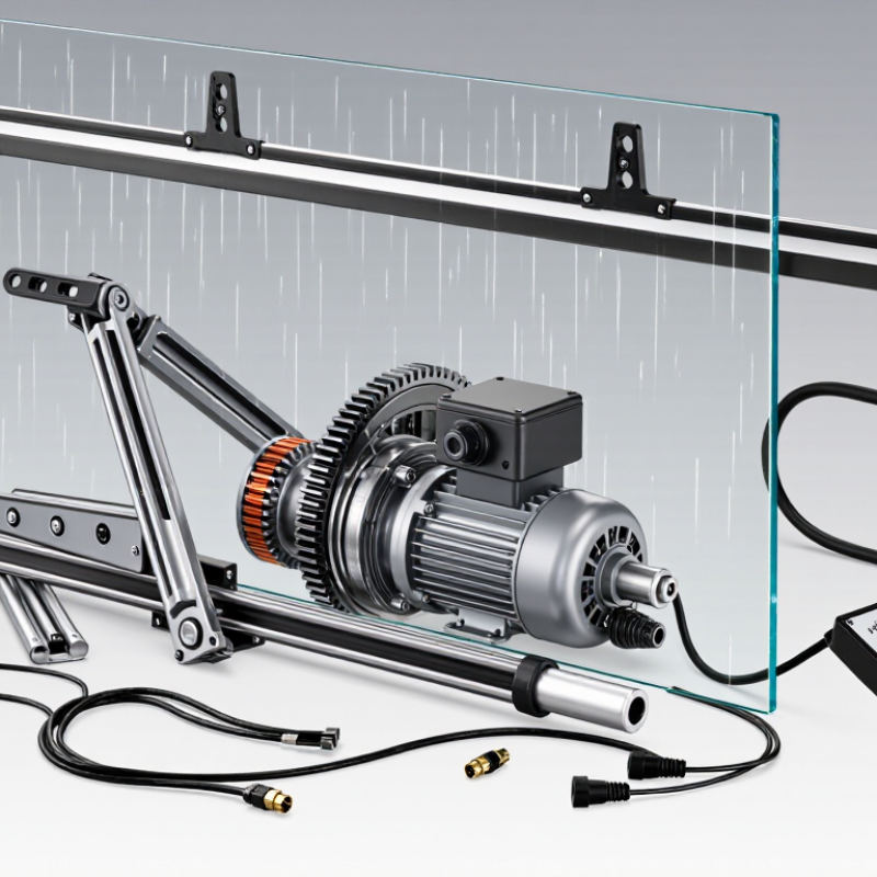
Table of Contents [Hide]
Define Wiper Motor Equipment: Components, Types, and 12 V/24 V Systems
Wiper motor equipment is the powered assembly that moves windshield wiper blades. It converts electrical energy into controlled mechanical motion. A typical unit includes a motor, gearbox, crank arm, linkage, shaft, and control connector. Some systems also include relays, fuses, position sensors, or washer-pump controls. These components usually sit behind the windshield cowl, where moisture and dust can collect. In practical inspections, worn linkage bushings often cause more noise than the motor itself. That detail is easy to miss.
Common types include single-speed, two-speed, intermittent, and electronically controlled motors. Single-speed designs suit basic equipment. Two-speed units provide normal and fast wiping. Intermittent systems pause between wiping cycles. Electronic versions can adjust speed using sensors or control modules. A 12 V system is common in passenger vehicles and compact equipment. A 24 V system is more suitable for larger vehicles and industrial machinery. Voltage must match. Incorrect voltage can overheat windings, damage controls, or produce weak movement.
When the switch sends power, the motor begins rotating. Its gearbox reduces speed and increases torque. The crank converts rotary motion into back-and-forth movement. The linkage then moves the wiper shafts across the glass. Limit contacts help return the blades to their parked position. During diagnosis, measure voltage under load, not only at rest. Check the ground path, fuse, connector, and linkage resistance. Listen for clicking, grinding, or delayed movement. A motor may appear defective when the linkage is actually seized. Technicians should question the first assumption.

© Copyright - Pro Tool & Supply - Site by SVM E-Marketing Solutions - Sitemap
- Privacy policy