- Products
- Air Compressors & Air Tools
- Climate Control
- Compaction Equipment
- Concrete Cutting Tools & Equipment
- Concrete and Masonry
- Demolition & Excavation
- Electrical & Mechanical
- Fasteners and Anchoring Adhesives
- Floor Protection
- Generators and Welders
- Hand Tools
- Heaters
- Janitorial and Office Supplies
- Jobsite Protection
- Ladders & Storage
- Lighting & Lighting Accessories
- Man Lifts
- Material Handling Equipment
- Power Tools
- Pressure Washers & Pumps
- Safety Gear
- Safety Products
- Saws
- Surface Preparation
- SEASONAL PRODUCTS
- Rentals
- Air Compressor and Air Tool Rentals
- Climate Control Rental
- Compaction Rentals
- Concrete Equipment Rentals
- Demolition & Excavation Equipment Rentals
- Concrete Floor Grinder Rentals
- General Construction Equipment Rentals
- Generator Rentals and Welder Rentals
- Heater Rentals
- Light Tower Rentals
- Man Lift Rentals in Massachusetts and Rhode Island
- Material Handling Equipment Rentals
- Pressure Washer & Pump Rentals
- Saw Rentals in New England
- SEASONAL PRODUCTS
- Products
- Air Compressors & Air Tools
- Climate Control
- Compaction Equipment
- Concrete Cutting Tools & Equipment
- Demolition & Excavation
- Electrical & Mechanical
- Floor Protection
- Generators and Welders
- Construction Heaters
- Construction Ladders, Staging, & Storage
- Construction Lighting
- Man Lifts
- Material Handling Equipment
- Industrial Janitorial and Office Supplies
- Pressure Washers & Pumps
- Construction Safety Products
- Construction Safety Gear
- Surface Preparation
- Building Protection
- Diesel Accessories
- Zero Emissions
- Rentals
- Air Compressor and Air Tool Rentals
- Climate Control Rental
- Compaction Rentals
- Concrete Equipment Rental
- Demolition & Excavation Equipment Rental
- General Construction Equipment Rental
- Generator Rentals and Welder Rentals
- Construction Heaters Rental
- Light Tower Rentals
- Man Lift Rentals
- Material Handling Equipment Rental
- Pressure Washer & Pump Rentals
- Saw Rentals in New England
- Concrete Floor Grinder Rentals
- Zero Emissions Rentals
- Repairs & Used
- Parts
- Blog
- Services
- Resources
- About Us
- Contact Us
Sales & Rental of Construction | Industrial Equipment & Supplies


Why Use a Filter Dryer for Compressor Systems?
A Filter Dryer For Compressor systems is a small component with a demanding responsibility. It removes moisture, acid, dirt, and metal particles from the refrigerant circuit. These contaminants can damage valves, restrict capillary tubes, and reduce compressor life. In practical service work, a blocked dryer may appear as poor cooling, unstable pressures, or an unusual temperature drop across its shell.
The component also protects the compressor after installation, repair, or burnout cleanup. A properly selected filter dryer can capture residual moisture before it reaches sensitive internal parts. Its capacity, connection size, refrigerant compatibility, and pressure rating must match the equipment. Check the manufacturer’s data carefully. Guesswork is expensive.
Technicians usually inspect the sight glass, measure pressure differences, and compare operating temperatures. A noticeable temperature drop across the dryer can indicate restriction. However, one reading rarely tells the whole story. Ambient temperature, charge level, airflow, and system load can create similar symptoms. This is where experience matters.
No filter dryer is a cure-all. It cannot compensate for poor evacuation, incorrect charging, or repeated moisture entry. That limitation deserves attention. Many failures blamed on the compressor begin with neglected installation practices. Replacing the dryer without finding the contamination source may only delay another breakdown.
Reliable maintenance combines manufacturer guidance, accurate instruments, and careful documentation. Choose a dryer with sufficient contaminant capacity, install it in the correct flow direction, and protect open tubing from humid air. Small details matter. When selected and installed correctly, a Filter Dryer For Compressor systems supports cleaner refrigerant, steadier performance, and more dependable long-term operation.
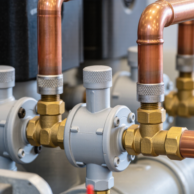
Table of Contents [Hide]
What Is a Filter Drier in a Compressor System?
A filter drier is a sealed protection device installed in a compressor system’s refrigerant circuit. It usually sits in the liquid line, near the expansion device. Inside, desiccant removes moisture, while a fine filter captures dirt, metal particles, and residue. Some models also help control acid after motor burnout.
Moisture can freeze at a narrow expansion valve. It can also create corrosion, copper plating, and lubricant problems. The ASHRAE Handbook—Refrigeration identifies moisture and contaminants as major causes of refrigeration-system failures. The U.S. Department of Energy reports that compressed-air leaks may waste 20–30% of compressor output. That figure concerns air systems, not refrigerant circuits, but it shows how small losses can become expensive. A filter drier cannot fix poor evacuation or contamination at the source. It is protection, not a cure.
Tips: Select the drier by refrigerant, flow capacity, moisture load, and allowable pressure drop. Replace it after a compressor burnout or major circuit opening. Check the sight glass, temperature difference, and system pressure after installation. AHRI Standard 740 supports disciplined refrigerant recovery and performance testing. Field work often reveals an uncomfortable truth: technicians sometimes choose by pipe size alone. That shortcut can restrict flow. Measure the system instead.

© Copyright - Pro Tool & Supply - Site by SVM E-Marketing Solutions - Sitemap
- Privacy policy