- Products
- Air Compressors & Air Tools
- Climate Control
- Compaction Equipment
- Concrete Cutting Tools & Equipment
- Concrete and Masonry
- Demolition & Excavation
- Electrical & Mechanical
- Fasteners and Anchoring Adhesives
- Floor Protection
- Generators and Welders
- Hand Tools
- Heaters
- Janitorial and Office Supplies
- Jobsite Protection
- Ladders & Storage
- Lighting & Lighting Accessories
- Man Lifts
- Material Handling Equipment
- Power Tools
- Pressure Washers & Pumps
- Safety Gear
- Safety Products
- Saws
- Surface Preparation
- SEASONAL PRODUCTS
- Rentals
- Air Compressor and Air Tool Rentals
- Climate Control Rental
- Compaction Rentals
- Concrete Equipment Rentals
- Demolition & Excavation Equipment Rentals
- Concrete Floor Grinder Rentals
- General Construction Equipment Rentals
- Generator Rentals and Welder Rentals
- Heater Rentals
- Light Tower Rentals
- Man Lift Rentals in Massachusetts and Rhode Island
- Material Handling Equipment Rentals
- Pressure Washer & Pump Rentals
- Saw Rentals in New England
- SEASONAL PRODUCTS
- Products
- Air Compressors & Air Tools
- Climate Control
- Compaction Equipment
- Concrete Cutting Tools & Equipment
- Demolition & Excavation
- Electrical & Mechanical
- Floor Protection
- Generators and Welders
- Construction Heaters
- Construction Ladders, Staging, & Storage
- Construction Lighting
- Man Lifts
- Material Handling Equipment
- Industrial Janitorial and Office Supplies
- Pressure Washers & Pumps
- Construction Safety Products
- Construction Safety Gear
- Surface Preparation
- Building Protection
- Diesel Accessories
- Zero Emissions
- Rentals
- Air Compressor and Air Tool Rentals
- Climate Control Rental
- Compaction Rentals
- Concrete Equipment Rental
- Demolition & Excavation Equipment Rental
- General Construction Equipment Rental
- Generator Rentals and Welder Rentals
- Construction Heaters Rental
- Light Tower Rentals
- Man Lift Rentals
- Material Handling Equipment Rental
- Pressure Washer & Pump Rentals
- Saw Rentals in New England
- Concrete Floor Grinder Rentals
- Zero Emissions Rentals
- Repairs & Used
- Parts
- Blog
- Services
- Resources
- About Us
- Contact Us
Sales & Rental of Construction | Industrial Equipment & Supplies


Why Are Grounding Kits Essential for Global Buyers?
Why Are Grounding Kits Essential for Global Buyers?
Grounding Kits are small components with serious safety responsibilities. They connect electrical equipment, structures, or cable systems to an intentional earth path. This path helps control fault current, static buildup, and transient overvoltage. The World Meteorological Organization reports approximately 24,000 lightning deaths and 240,000 injuries worldwide each year. Grounding cannot eliminate lightning risk. It can, however, support safer current dissipation when systems are correctly designed.
Global buyers face more than a simple product comparison. IEC 60364-4-41 emphasizes protection against electric shock through automatic supply disconnection and protective earthing. NFPA 70, the National Electrical Code, also defines requirements for grounding and bonding in many installations. IEEE Std 80 provides engineering guidance for grounding substations and managing touch and step potentials. These references show why kit selection must consider fault levels, soil resistivity, conductor material, corrosion exposure, and local installation rules.
Details matter. A copper lug may look suitable, yet its plating, hole size, and pressure rating can determine long-term performance. Stainless steel hardware may suit coastal facilities better than untreated carbon steel. Buyers should request test reports, material certificates, installation instructions, and evidence of compatibility with the target standard. UL 467 is often relevant for grounding and bonding equipment in North American projects, while IEC-based markets may require different verification routes. Certification alone is not a complete answer. That is the uncomfortable part. A compliant kit can still fail when installed loosely, buried in unsuitable soil, or paired with incompatible metals. Experienced procurement teams therefore evaluate the complete grounding design, not only the package label.
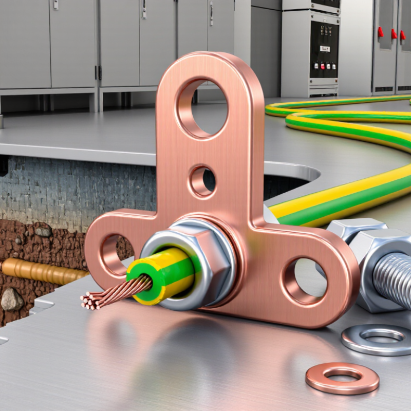
Table of Contents [Hide]
What Grounding Kits Are and How They Work
Grounding kits are practical sets of conductors, clamps, rods, connectors, and protective hardware. They connect electrical equipment to the earth. The goal is simple: provide a controlled path for unwanted current.
When a fault occurs, current travels through this path instead of remaining on exposed metal surfaces. This reduces shock risks and helps protective devices operate quickly. A grounding kit may also limit damage from surges and unstable electrical conditions. However, performance depends on correct installation. Soil moisture, corrosion, conductor length, and connection quality all matter. A kit can look complete, yet still fail because one connection was overlooked. That detail is easy to underestimate.
For global buyers, check material specifications, conductor sizes, and testing documents before purchase. Copper, galvanized steel, and stainless steel perform differently in wet or salty environments. Installation drawings should match the equipment and site conditions. Local electrical requirements may also affect rod depth, spacing, and inspection procedures. A qualified installer should measure soil resistance after installation. Do not assume the same kit suits every country or building. Field conditions often change the result.
Tips: Confirm compatibility with the site’s voltage and soil conditions. Inspect clamps for tight, clean contact. Keep records of resistance measurements and maintenance checks. Review the design when the site expands or equipment changes. Small gaps in planning can create serious grounding problems.

© Copyright - Pro Tool & Supply - Site by SVM E-Marketing Solutions - Sitemap
- Privacy policy