- Products
- Air Compressors & Air Tools
- Climate Control
- Compaction Equipment
- Concrete Cutting Tools & Equipment
- Concrete and Masonry
- Demolition & Excavation
- Electrical & Mechanical
- Fasteners and Anchoring Adhesives
- Floor Protection
- Generators and Welders
- Hand Tools
- Heaters
- Janitorial and Office Supplies
- Jobsite Protection
- Ladders & Storage
- Lighting & Lighting Accessories
- Man Lifts
- Material Handling Equipment
- Power Tools
- Pressure Washers & Pumps
- Safety Gear
- Safety Products
- Saws
- Surface Preparation
- SEASONAL PRODUCTS
- Rentals
- Air Compressor and Air Tool Rentals
- Climate Control Rental
- Compaction Rentals
- Concrete Equipment Rentals
- Demolition & Excavation Equipment Rentals
- Concrete Floor Grinder Rentals
- General Construction Equipment Rentals
- Generator Rentals and Welder Rentals
- Heater Rentals
- Light Tower Rentals
- Man Lift Rentals in Massachusetts and Rhode Island
- Material Handling Equipment Rentals
- Pressure Washer & Pump Rentals
- Saw Rentals in New England
- SEASONAL PRODUCTS
- Products
- Air Compressors & Air Tools
- Climate Control
- Compaction Equipment
- Concrete Cutting Tools & Equipment
- Demolition & Excavation
- Electrical & Mechanical
- Floor Protection
- Generators and Welders
- Construction Heaters
- Construction Ladders, Staging, & Storage
- Construction Lighting
- Man Lifts
- Material Handling Equipment
- Industrial Janitorial and Office Supplies
- Pressure Washers & Pumps
- Construction Safety Products
- Construction Safety Gear
- Surface Preparation
- Building Protection
- Diesel Accessories
- Zero Emissions
- Rentals
- Air Compressor and Air Tool Rentals
- Climate Control Rental
- Compaction Rentals
- Concrete Equipment Rental
- Demolition & Excavation Equipment Rental
- General Construction Equipment Rental
- Generator Rentals and Welder Rentals
- Construction Heaters Rental
- Light Tower Rentals
- Man Lift Rentals
- Material Handling Equipment Rental
- Pressure Washer & Pump Rentals
- Saw Rentals in New England
- Concrete Floor Grinder Rentals
- Zero Emissions Rentals
- Repairs & Used
- Parts
- Blog
- Services
- Resources
- About Us
- Contact Us
Sales & Rental of Construction | Industrial Equipment & Supplies


Why Choose Precision Mold Components?
Why Choose Precision Mold Components?
A molded part may look simple after it leaves the press. Inside the tool, however, guide pins, bushings, ejector pins, and cavity inserts must work together through repeated cycles. Small errors can show up as flash, uneven dimensions, sticking parts, or avoidable downtime. Precision Mold Components help control these risks by supporting accurate alignment, repeatable movement, and consistent part formation. The details matter.
Market demand gives useful context, but it is not proof that every mold needs premium components. Grand View Research’s Injection Molded Plastics Market Size, Share & Trends Analysis Report estimated the global market at USD 387.5 billion in 2023, with projected growth from 2024 to 2030. That scale reflects broad use across industries, not a guaranteed return on any specific tooling choice. Buyers still need to match component materials, tolerances, coatings, and serviceability to the resin, cycle conditions, and expected production volume.
A well-chosen component can reduce wear and help keep a mold stable across long runs. For example, a properly fitted guide system can limit misalignment, while a suitable ejector pin can release parts without marking them. Yet a tighter tolerance is not automatically better. It may raise cost without improving the finished product. The choice is not automatic. Review drawings, operating conditions, and maintenance access with an experienced mold maker. Precision should solve a measurable problem—and sometimes the first specification needs another look.
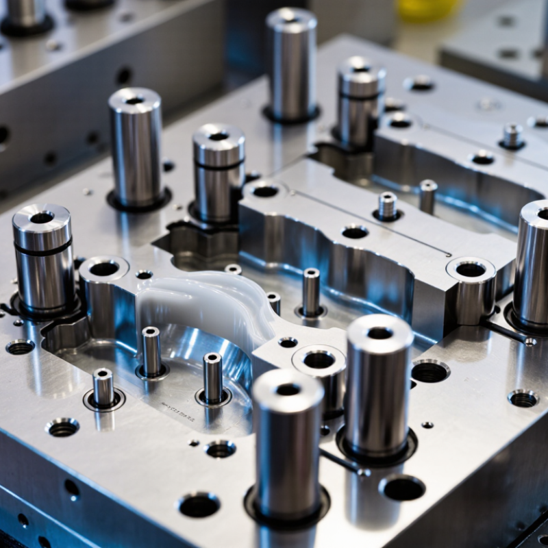
Table of Contents [Hide]
What Are Precision Mold Components?
Why Choose Precision Mold Components?
What Are Precision Mold Components?
Precision mold components are the fitted parts that shape, guide, cool, and release a molded product. They include core and cavity inserts, guide pins and bushings, ejector pins, sliders, and lifters. Each has a defined job. The core and cavity form the part’s surfaces; guide elements keep the mold halves aligned, while ejectors help release the finished piece. Precision means controlling dimensions, surface finish, material, and fit to suit the mold design and production conditions. It does not mean making every feature as tight as possible.
A small mismatch can leave flash along an edge or cause uneven wear. For example, a guide pin that binds as the mold warms can affect alignment over repeated cycles. Material choice and maintenance matter, too. Grand View Research’s 2024 report valued the global injection-molded plastics market at USD 284.4 billion in 2023 and projected 4.7% annual growth through 2030. That scale makes repeatable tooling important, but market growth alone does not prove a component is suitable. Teams should check drawings, operating temperatures, resin behavior, and inspection records. A perfect-looking specification can still miss real shop-floor conditions.

© Copyright - Pro Tool & Supply - Site by SVM E-Marketing Solutions - Sitemap
- Privacy policy