- Products
- Air Compressors & Air Tools
- Climate Control
- Compaction Equipment
- Concrete Cutting Tools & Equipment
- Concrete and Masonry
- Demolition & Excavation
- Electrical & Mechanical
- Fasteners and Anchoring Adhesives
- Floor Protection
- Generators and Welders
- Hand Tools
- Heaters
- Janitorial and Office Supplies
- Jobsite Protection
- Ladders & Storage
- Lighting & Lighting Accessories
- Man Lifts
- Material Handling Equipment
- Power Tools
- Pressure Washers & Pumps
- Safety Gear
- Safety Products
- Saws
- Surface Preparation
- SEASONAL PRODUCTS
- Rentals
- Air Compressor and Air Tool Rentals
- Climate Control Rental
- Compaction Rentals
- Concrete Equipment Rentals
- Demolition & Excavation Equipment Rentals
- Concrete Floor Grinder Rentals
- General Construction Equipment Rentals
- Generator Rentals and Welder Rentals
- Heater Rentals
- Light Tower Rentals
- Man Lift Rentals in Massachusetts and Rhode Island
- Material Handling Equipment Rentals
- Pressure Washer & Pump Rentals
- Saw Rentals in New England
- SEASONAL PRODUCTS
- Products
- Air Compressors & Air Tools
- Climate Control
- Compaction Equipment
- Concrete Cutting Tools & Equipment
- Demolition & Excavation
- Electrical & Mechanical
- Floor Protection
- Generators and Welders
- Construction Heaters
- Construction Ladders, Staging, & Storage
- Construction Lighting
- Man Lifts
- Material Handling Equipment
- Industrial Janitorial and Office Supplies
- Pressure Washers & Pumps
- Construction Safety Products
- Construction Safety Gear
- Surface Preparation
- Building Protection
- Diesel Accessories
- Zero Emissions
- Rentals
- Air Compressor and Air Tool Rentals
- Climate Control Rental
- Compaction Rentals
- Concrete Equipment Rental
- Demolition & Excavation Equipment Rental
- General Construction Equipment Rental
- Generator Rentals and Welder Rentals
- Construction Heaters Rental
- Light Tower Rentals
- Man Lift Rentals
- Material Handling Equipment Rental
- Pressure Washer & Pump Rentals
- Saw Rentals in New England
- Concrete Floor Grinder Rentals
- Zero Emissions Rentals
- Repairs & Used
- Parts
- Blog
- Services
- Resources
- About Us
- Contact Us
Sales & Rental of Construction | Industrial Equipment & Supplies


Why Choose a 4 Pin Female Connector?
Why Choose a 4 Pin Female Connector?
The 4 Pin Female Connector remains a practical choice for compact power and signal systems. Its four contacts can carry power, ground, and two controlled signal paths. That arrangement supports sensors, LED modules, industrial controls, and small automation assemblies. It also simplifies inspection. Each contact has a clear function.
Market evidence supports this continuing demand. Grand View Research reports steady growth in the global connectors market, driven by automotive electronics, communications equipment, and industrial automation. Bishop & Associates also identifies connectors as essential components in expanding electronic systems. These reports do not prove that four pins fit every design. They show a broader reality: reliable interconnection is becoming more important.
John J. Nardone, president of Bishop & Associates, has described connectors as “critical components in every electronic system.” That perspective matters when selecting a 4 Pin Female Connector. Engineers must examine contact plating, current rating, pitch, locking strength, and mating cycles. A connector that feels secure on a workbench may loosen under vibration. Small details matter.
Consider a control cabinet with limited space. A keyed female housing can prevent reversed mating. Gold-plated contacts may reduce oxidation in demanding environments. Strain relief can protect the cable during repeated movement. These benefits are practical, not decorative.
Still, four pins are not automatically better. Higher pin counts may suit data-rich devices. Lower counts may reduce cost and assembly time. The right choice depends on measured electrical and mechanical requirements. That is where many product comparisons become too confident. A datasheet, test sample, and application review should guide the final decision.
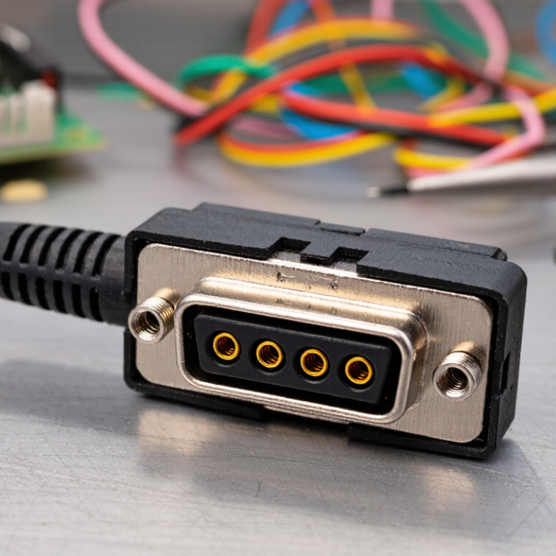
Table of Contents [Hide]
4-Pin Female Connectors Defined: Contact Layout, Polarity, and IEC 60512
Why Choose a 4 Pin Female Connector?
A 4-pin female connector uses four receptacle contacts to carry power, signals, or both. Its contact layout may be linear, square, or circular, depending on the housing design. The arrangement affects wiring space, mating direction, and inspection access. Female contacts receive male pins inside protected cavities, reducing accidental contact during handling. Small detail, but important.
Polarity is not automatic. A keyed housing, offset contact, or shaped latch can prevent reverse mating. However, pin numbering still varies between products. Never trust appearance alone. Check the technical drawing, cavity markings, and wiring schedule before assembly. IEC 60512 provides standardized test methods for connector performance, including contact resistance, insulation resistance, mechanical operation, and environmental endurance. It does not define one universal four-pin layout or guarantee suitability for every application. That distinction is often missed.
Tips: Confirm pin one with a meter and the manufacturer’s drawing. Inspect the contact position under bright light. A loose crimp can pass an initial test, then fail under vibration. For field wiring, record polarity beside the connector, not only in a separate manual. I sometimes find layout diagrams surprisingly unclear, so photographing the verified assembly can prevent later mistakes.

© Copyright - Pro Tool & Supply - Site by SVM E-Marketing Solutions - Sitemap
- Privacy policy