- Products
- Air Compressors & Air Tools
- Climate Control
- Compaction Equipment
- Concrete Cutting Tools & Equipment
- Concrete and Masonry
- Demolition & Excavation
- Electrical & Mechanical
- Fasteners and Anchoring Adhesives
- Floor Protection
- Generators and Welders
- Hand Tools
- Heaters
- Janitorial and Office Supplies
- Jobsite Protection
- Ladders & Storage
- Lighting & Lighting Accessories
- Man Lifts
- Material Handling Equipment
- Power Tools
- Pressure Washers & Pumps
- Safety Gear
- Safety Products
- Saws
- Surface Preparation
- SEASONAL PRODUCTS
- Rentals
- Air Compressor and Air Tool Rentals
- Climate Control Rental
- Compaction Rentals
- Concrete Equipment Rentals
- Demolition & Excavation Equipment Rentals
- Concrete Floor Grinder Rentals
- General Construction Equipment Rentals
- Generator Rentals and Welder Rentals
- Heater Rentals
- Light Tower Rentals
- Man Lift Rentals in Massachusetts and Rhode Island
- Material Handling Equipment Rentals
- Pressure Washer & Pump Rentals
- Saw Rentals in New England
- SEASONAL PRODUCTS
- Products
- Air Compressors & Air Tools
- Climate Control
- Compaction Equipment
- Concrete Cutting Tools & Equipment
- Demolition & Excavation
- Electrical & Mechanical
- Floor Protection
- Generators and Welders
- Construction Heaters
- Construction Ladders, Staging, & Storage
- Construction Lighting
- Man Lifts
- Material Handling Equipment
- Industrial Janitorial and Office Supplies
- Pressure Washers & Pumps
- Construction Safety Products
- Construction Safety Gear
- Surface Preparation
- Building Protection
- Diesel Accessories
- Zero Emissions
- Rentals
- Air Compressor and Air Tool Rentals
- Climate Control Rental
- Compaction Rentals
- Concrete Equipment Rental
- Demolition & Excavation Equipment Rental
- General Construction Equipment Rental
- Generator Rentals and Welder Rentals
- Construction Heaters Rental
- Light Tower Rentals
- Man Lift Rentals
- Material Handling Equipment Rental
- Pressure Washer & Pump Rentals
- Saw Rentals in New England
- Concrete Floor Grinder Rentals
- Zero Emissions Rentals
- Repairs & Used
- Parts
- Blog
- Services
- Resources
- About Us
- Contact Us
Sales & Rental of Construction | Industrial Equipment & Supplies


Top Hydraulic Fittings Manufacturers and Suppliers
Hydraulic Fittings support the reliable movement of oil under pressure. They connect pumps, valves, hoses, cylinders, and control systems. A small thread error can cause leakage, downtime, or serious equipment damage. That is why this market deserves more than a simple supplier list.
Grand View Research estimates that the global hydraulic fittings market reached approximately USD 1.7 billion in 2023. Its report also projects steady growth through 2030, supported by construction machinery, agricultural equipment, mining, and industrial automation. MarketsandMarkets reports similar expansion across hydraulic hose and connection systems, driven by replacement demand and stricter efficiency requirements. Figures vary by research method. That matters.
The best manufacturers usually demonstrate more than production scale. They show material traceability, pressure testing, dimensional control, corrosion resistance, and documented compliance with standards such as ISO 8434 and SAE specifications. Parker Hannifin, Eaton, Gates, Stauff, and Hydraulics Inc. are frequently recognized in industrial supply discussions, although regional specialists can offer faster customization or shorter delivery times.
As Eric Lanke, President and CEO of the National Fluid Power Association, has stated, “Fluid power is the hidden giant of American manufacturing.” That observation explains the importance of fittings. They may look like small steel components, yet they influence system safety and operating life.
Selection still requires judgment. Port size alone is not enough. Engineers should examine pressure ratings, temperature, fluid compatibility, thread type, installation space, and supplier quality records. The lowest quotation may become the most expensive choice. This guide compares leading Hydraulic Fittings manufacturers and suppliers through those practical criteria, while recognizing one uncomfortable truth: product data is not always presented consistently.
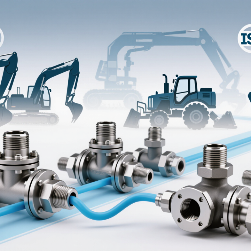
Table of Contents [Hide]
What Hydraulic Fittings Are and How They Work
Top Hydraulic Fittings Manufacturers and Suppliers
What Hydraulic Fittings Are and How They Work
Hydraulic fittings connect hoses, tubes, valves, and actuators within a pressurized fluid circuit. Their job seems simple. It is not. A fitting must guide oil smoothly, resist pressure, and prevent leakage at the connection point. Common designs include threaded, compression, flange, and quick-connect fittings. Each design suits different pressure levels, installation spaces, and maintenance needs.
Inside a fitting, sealing depends on thread geometry, an O-ring, or a metal-to-metal seat. The fitting does not create hydraulic power. It preserves it. Poor alignment can damage seals and create turbulence near the connection. ISO 4413 recommends controlling leakage, pressure risks, and stored hydraulic energy during system design. This matters because hydraulic systems can operate above 200 bar, even in compact equipment.
Grand View Research valued the global hydraulic equipment market at approximately USD 49.3 billion in 2023. That scale reflects continuing demand for reliable fluid-power components. However, market growth does not make every fitting suitable. Selecting by size alone is a common mistake. Engineers should check working pressure, temperature, fluid compatibility, thread standard, and vibration exposure. ISO 6162 also defines dimensions for several hydraulic flange connections. In practice, a fitting may look correct yet fail after repeated pressure pulses. That uncomfortable detail deserves more attention.
Top Hydraulic Fittings Manufacturers and Suppliers - What Hydraulic Fittings Are and How They Work
| Fitting Type | Primary Function | Connection Method | Common Materials | Typical Pressure Capability | How It Works | Typical Applications | Important Selection Criteria |
|---|---|---|---|---|---|---|---|
| Straight Adapter | Connects two components with different or matching connection ends. | Threaded, tube, or hose connections. | Carbon steel, stainless steel, brass. | Varies by design; many industrial versions are rated from approximately 150 to 6,000 psi. | Creates a sealed transition between two hydraulic ports while maintaining the fluid passage. | Power units, manifolds, cylinders, pumps, and hose assemblies. | Thread standard, pressure rating, fluid compatibility, and port size. |
| Elbow Fitting | Changes the direction of a hydraulic line. | Usually threaded or tube-based; common angles are 45° and 90°. | Carbon steel, stainless steel, brass. | Common ratings range from approximately 150 to 6,000 psi, depending on construction. | Redirects fluid flow around equipment or through confined spaces without requiring a sharp hose bend. | Mobile equipment, industrial machinery, agricultural systems. | Bend angle, flow path, space limitations, pressure drop, and vibration resistance. |
| Tee Fitting | Splits one hydraulic flow path into two or combines two paths. | Threaded, tube, or hose-end connections. | Steel, stainless steel, brass. | Selected according to port design; high-pressure steel versions are widely used. | Provides a three-port junction for distributing or collecting pressurized hydraulic fluid. | Control circuits, lubrication systems, test points, and manifold assemblies. | Port orientation, flow capacity, pressure rating, and potential turbulence. |
| Cross Fitting | Connects four hydraulic lines at a single junction. | Threaded or tube connections. | Steel and stainless steel are common choices. | Depends on the port size, material, and pressure class. | Allows hydraulic fluid to pass between four connected branches in a compact layout. | Complex hydraulic circuits and compact manifold arrangements. | Balanced flow requirements, available space, port compatibility, and service access. |
| Bulkhead Fitting | Passes a hydraulic connection through a panel, wall, or frame. | Threaded body secured with a locknut, often with sealing washers. | Plated steel, stainless steel, brass. | Available for low-, medium-, and high-pressure circuits depending on the design. | Maintains a sealed fluid passage while mechanically securing the line to a fixed panel. | Vehicle frames, hydraulic tanks, machine enclosures, and control cabinets. | Panel thickness, sealing arrangement, vibration, corrosion exposure, and access for tightening. |
| Hose End Fitting | Connects a flexible hydraulic hose to equipment or another hose assembly. | Crimped, reusable, or field-attachable hose connection. | Steel, stainless steel, and thermoplastic-compatible materials. | Must match the hose assembly rating; hydraulic hose systems commonly range from several hundred to several thousand psi. | Uses a sleeve, ferrule, or gripping mechanism to retain the hose and seal the fluid path. | Mobile machinery, lifting equipment, presses, and construction equipment. | Hose size, working pressure, bend radius, temperature, and assembly method. |
| Quick-Disconnect Coupling | Connects and disconnects hydraulic lines quickly without tools. | Ball, poppet, or flat-face quick-connect mechanism. | Hardened steel, stainless steel, brass. | Common industrial ranges extend from approximately 1,000 to 10,000 psi, depending on series. | Internal valves open when coupled and close when disconnected to limit fluid loss and contamination. | Attachments, agricultural implements, test equipment, and service tools. | Pressure under connection, flow capacity, leakage control, contamination protection, and interchangeability. |
| Flange Adapter | Connects large-bore hydraulic lines and components where high flow or high pressure is required. | Bolted flange with an O-ring or other face seal. | Carbon steel and stainless steel. | Often used in medium- to very-high-pressure systems; rating depends on flange series and size. | Bolts clamp the flange faces together while the seal prevents fluid leakage through the joint. | Pumps, motors, valves, presses, and heavy-duty industrial systems. | Flange standard, nominal size, bolt pattern, seal material, and tightening torque. |
| O-Ring Face Seal Fitting | Creates a reliable leak-resistant connection for pressurized hydraulic systems. | Threaded connection sealed by an O-ring on the fitting face. | Steel and stainless steel; elastomer selected for the fluid and temperature. | Commonly suitable for medium- and high-pressure hydraulic service when correctly installed. | The compressed O-ring forms a face seal, while the threads provide mechanical retention. | Industrial machinery, mobile hydraulics, manifolds, and high-vibration systems. | O-ring compound, groove condition, thread size, installation torque, and temperature. |
| Tube Compression Fitting | Connects rigid hydraulic tubing without welding or brazing. | Ferrule or sleeve compressed onto the tube. | Steel, stainless steel, and brass. | Pressure capacity varies significantly with tube material, wall thickness, and fitting size. | Tightening drives the ferrule into the tube to create a mechanical grip and fluid seal. | Instrumentation, control lines, lubrication circuits, and compact hydraulic systems. | Tube outside diameter, wall thickness, material hardness, vibration, and reusability. |
Note: Pressure values are general industry ranges rather than universal ratings. Always confirm the manufacturer’s technical data, applicable connection standard, hose or tube rating, fluid compatibility, and installation requirements before selecting a hydraulic fitting.

© Copyright - Pro Tool & Supply - Site by SVM E-Marketing Solutions - Sitemap
- Privacy policy