- Products
- Air Compressors & Air Tools
- Climate Control
- Compaction Equipment
- Concrete Cutting Tools & Equipment
- Concrete and Masonry
- Demolition & Excavation
- Electrical & Mechanical
- Fasteners and Anchoring Adhesives
- Floor Protection
- Generators and Welders
- Hand Tools
- Heaters
- Janitorial and Office Supplies
- Jobsite Protection
- Ladders & Storage
- Lighting & Lighting Accessories
- Man Lifts
- Material Handling Equipment
- Power Tools
- Pressure Washers & Pumps
- Safety Gear
- Safety Products
- Saws
- Surface Preparation
- SEASONAL PRODUCTS
- Rentals
- Air Compressor and Air Tool Rentals
- Climate Control Rental
- Compaction Rentals
- Concrete Equipment Rentals
- Demolition & Excavation Equipment Rentals
- Concrete Floor Grinder Rentals
- General Construction Equipment Rentals
- Generator Rentals and Welder Rentals
- Heater Rentals
- Light Tower Rentals
- Man Lift Rentals in Massachusetts and Rhode Island
- Material Handling Equipment Rentals
- Pressure Washer & Pump Rentals
- Saw Rentals in New England
- SEASONAL PRODUCTS
- Products
- Air Compressors & Air Tools
- Climate Control
- Compaction Equipment
- Concrete Cutting Tools & Equipment
- Demolition & Excavation
- Electrical & Mechanical
- Floor Protection
- Generators and Welders
- Construction Heaters
- Construction Ladders, Staging, & Storage
- Construction Lighting
- Man Lifts
- Material Handling Equipment
- Industrial Janitorial and Office Supplies
- Pressure Washers & Pumps
- Construction Safety Products
- Construction Safety Gear
- Surface Preparation
- Building Protection
- Diesel Accessories
- Zero Emissions
- Rentals
- Air Compressor and Air Tool Rentals
- Climate Control Rental
- Compaction Rentals
- Concrete Equipment Rental
- Demolition & Excavation Equipment Rental
- General Construction Equipment Rental
- Generator Rentals and Welder Rentals
- Construction Heaters Rental
- Light Tower Rentals
- Man Lift Rentals
- Material Handling Equipment Rental
- Pressure Washer & Pump Rentals
- Saw Rentals in New England
- Concrete Floor Grinder Rentals
- Zero Emissions Rentals
- Repairs & Used
- Parts
- Blog
- Services
- Resources
- About Us
- Contact Us
Sales & Rental of Construction | Industrial Equipment & Supplies


What Is a Terminal Block and What Is It Used For?
A Terminal Block is a practical electrical connector that joins wires securely without soldering. It usually contains an insulated body, metal terminals, and screws or spring clamps. Inside a control cabinet, it can connect a power supply to sensors, relays, motors, or other field devices. The arrangement looks simple. Its role is not.
Terminal blocks help technicians organize circuits, separate wiring functions, and simplify testing or maintenance. A labeled row can make a crowded cabinet easier to understand. For example, one section may carry 24-volt control signals, while another handles protective earth connections. Clear spacing and identification reduce the chance of connecting a wire to the wrong point. That small detail matters during commissioning.
Different designs serve different conditions. Feed-through blocks pass conductors from one side to another. Ground terminal blocks connect wiring to a mounting rail or grounding system. Fuse and disconnect versions add protection or isolation for specific circuits. Selection depends on wire size, current rating, voltage, temperature, vibration, and installation space. Manufacturer data should always be checked.
Real installations often reveal overlooked details. A screw may loosen under vibration. A stripped conductor may create heat. A poorly labeled terminal can delay fault finding for hours. Terminal blocks are not automatically safe simply because they are common. Correct stripping, tightening torque, insulation clearance, and inspection remain essential. Even experienced installers sometimes underestimate cabinet airflow or future expansion. That mistake deserves review.
Understanding what a Terminal Block is helps engineers and electricians design cleaner, more reliable connections. It also supports safer troubleshooting when equipment must be inspected or modified.
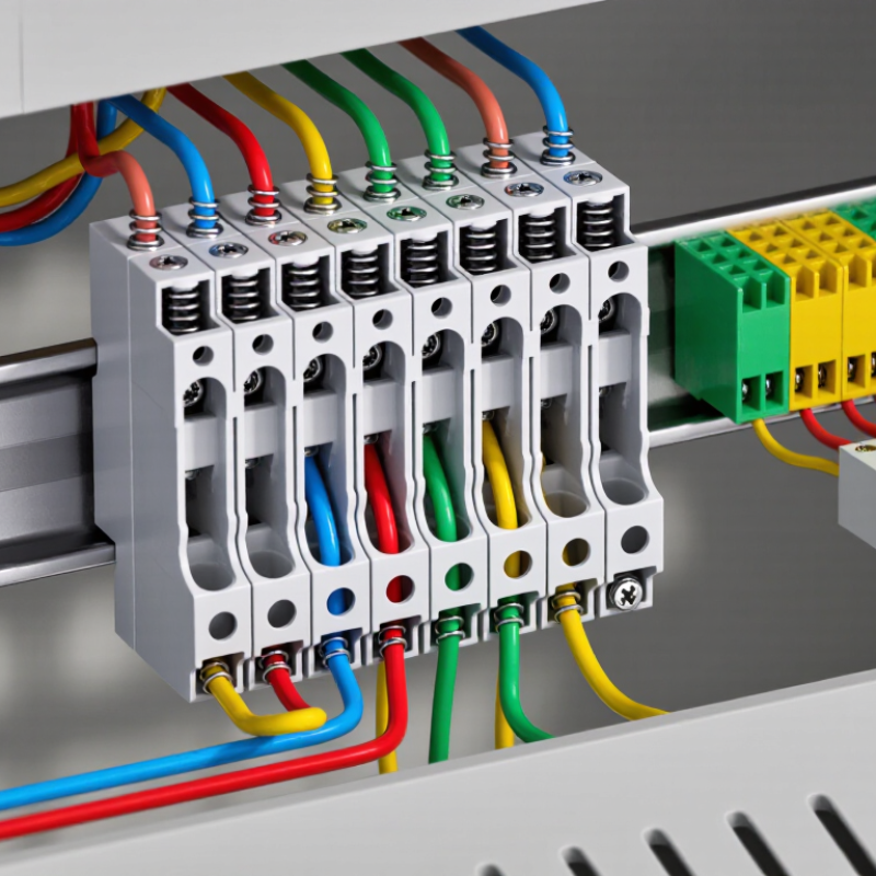
Table of Contents [Hide]
What Is a Terminal Block? Definition Under IEC 60947-7-1
Under IEC 60947-7-1, a terminal block is a low-voltage electrical accessory designed to connect copper conductors securely. It provides an organized connection point between incoming cables, control circuits, and equipment wiring.
Many terminal blocks use screw clamps or spring-clamp mechanisms. They may also mount on a supporting rail inside a control cabinet.
The standard focuses on terminal blocks for copper conductors used in industrial and similar installations. It addresses practical safety requirements, including electrical insulation, temperature rise, mechanical strength, and resistance to abnormal heating. Markings such as rated voltage and current help engineers select a suitable device.
A terminal block is used to distribute power, join circuits, and simplify inspection or maintenance. For example, one side may receive a supply cable, while the other side connects to a motor starter or sensor.
Clear labels and separation plates can reduce wiring errors. Small details matter.
A conductor must be stripped correctly and inserted fully into the clamping area. Excessive tightening can damage the conductor, while insufficient tightening may create heat at the contact point.
IEC 60947-7-1 supports reliable design, but it cannot correct poor installation practices. Real projects also reveal a limitation: identical-looking blocks may have different ratings, spacing, or conductor ranges. Checking the technical marking and installation conditions remains essential.

© Copyright - Pro Tool & Supply - Site by SVM E-Marketing Solutions - Sitemap
- Privacy policy