- Products
- Air Compressors & Air Tools
- Climate Control
- Compaction Equipment
- Concrete Cutting Tools & Equipment
- Concrete and Masonry
- Demolition & Excavation
- Electrical & Mechanical
- Fasteners and Anchoring Adhesives
- Floor Protection
- Generators and Welders
- Hand Tools
- Heaters
- Janitorial and Office Supplies
- Jobsite Protection
- Ladders & Storage
- Lighting & Lighting Accessories
- Man Lifts
- Material Handling Equipment
- Power Tools
- Pressure Washers & Pumps
- Safety Gear
- Safety Products
- Saws
- Surface Preparation
- SEASONAL PRODUCTS
- Rentals
- Air Compressor and Air Tool Rentals
- Climate Control Rental
- Compaction Rentals
- Concrete Equipment Rentals
- Demolition & Excavation Equipment Rentals
- Concrete Floor Grinder Rentals
- General Construction Equipment Rentals
- Generator Rentals and Welder Rentals
- Heater Rentals
- Light Tower Rentals
- Man Lift Rentals in Massachusetts and Rhode Island
- Material Handling Equipment Rentals
- Pressure Washer & Pump Rentals
- Saw Rentals in New England
- SEASONAL PRODUCTS
- Products
- Air Compressors & Air Tools
- Climate Control
- Compaction Equipment
- Concrete Cutting Tools & Equipment
- Demolition & Excavation
- Electrical & Mechanical
- Floor Protection
- Generators and Welders
- Construction Heaters
- Construction Ladders, Staging, & Storage
- Construction Lighting
- Man Lifts
- Material Handling Equipment
- Industrial Janitorial and Office Supplies
- Pressure Washers & Pumps
- Construction Safety Products
- Construction Safety Gear
- Surface Preparation
- Building Protection
- Diesel Accessories
- Zero Emissions
- Rentals
- Air Compressor and Air Tool Rentals
- Climate Control Rental
- Compaction Rentals
- Concrete Equipment Rental
- Demolition & Excavation Equipment Rental
- General Construction Equipment Rental
- Generator Rentals and Welder Rentals
- Construction Heaters Rental
- Light Tower Rentals
- Man Lift Rentals
- Material Handling Equipment Rental
- Pressure Washer & Pump Rentals
- Saw Rentals in New England
- Concrete Floor Grinder Rentals
- Zero Emissions Rentals
- Repairs & Used
- Parts
- Blog
- Services
- Resources
- About Us
- Contact Us
Sales & Rental of Construction | Industrial Equipment & Supplies


Top 10 Rotary Actuator Symbol Types Explained
Rotary Actuator Symbols look small, but they control how engineers interpret motion, ports, and energy paths. A circular arrow on a schematic may indicate rotation, direction, or an actuator function. The surrounding lines matter just as much.
The IEC 60617 graphical symbols database provides internationally recognized symbols for electrotechnical diagrams. ISO 1219-1 defines graphical symbols used in fluid power systems, including pneumatic and hydraulic components. These standards support consistent documentation across design offices, factories, and maintenance teams. In practice, a technician may identify a rotary actuator from a symbol before seeing the machine itself. A mislabeled port can still create confusion.
Automation continues to expand the need for clear drawings. The International Federation of Robotics reported 541,302 industrial robot installations worldwide in 2023. Many robotic cells use rotary actuators for gripping, indexing, positioning, and tool rotation. Each application depends on readable schematics. The wrong symbol can waste valuable troubleshooting time.
This guide explains the Top 10 Rotary Actuator Symbol Types Explained through practical visual details. It covers pneumatic, hydraulic, electric, double-acting, spring-return, and position-controlled forms. It also considers arrows, shafts, pressure lines, electrical terminals, and limit-switch markings. Symbols are not always perfectly consistent across software libraries. That deserves attention.
Engineers should verify the drawing against ISO, IEC, ISA, or project-specific conventions. A familiar icon may still be incomplete. Field experience shows that context often determines the correct interpretation. The goal is not memorization. It is safer, faster, and more reliable communication.
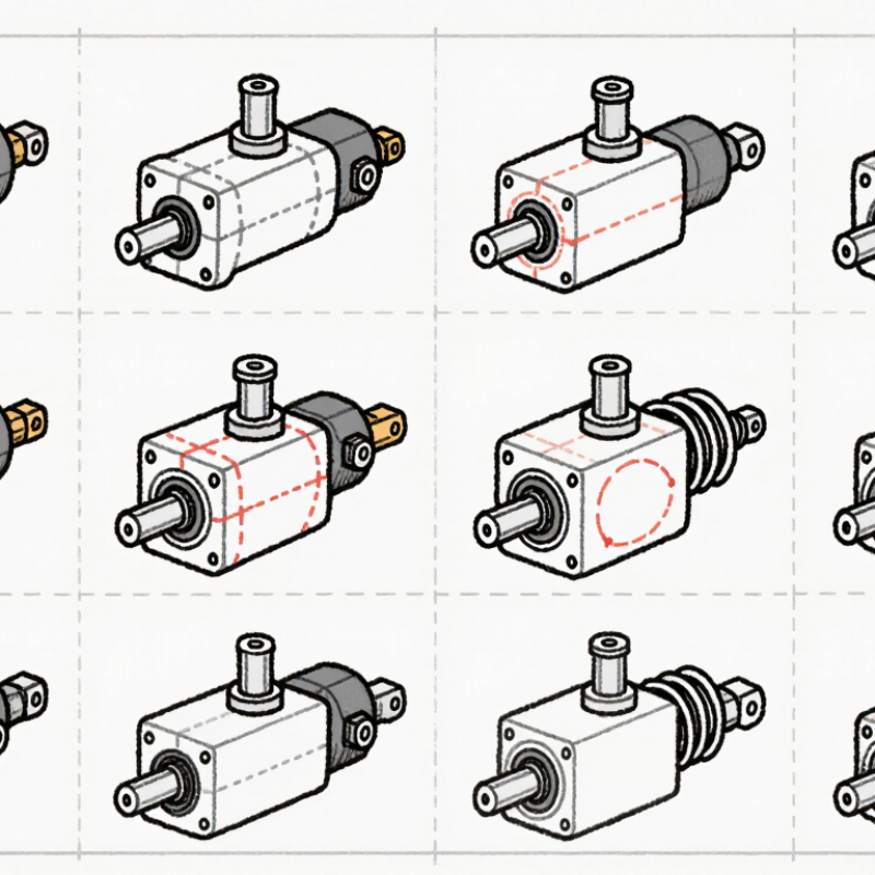
Table of Contents [Hide]
Rotary Actuator Symbols: Purpose, Structure, and Reading Principles
Top 10 Rotary Actuator Symbol Types Explained
Rotary Actuator Symbols: Purpose, Structure, and Reading Principles
Rotary actuator symbols translate movement into a compact visual language. They show rotation, torque, flow direction, and control method. In practical schematics, I read the symbol before checking the component list. This habit prevents costly wiring and piping errors.
The ten common types include fixed-displacement hydraulic motors, variable-displacement motors, pneumatic motors, rotary cylinders, vane actuators, rack-and-pinion actuators, single-acting actuators, double-acting actuators, reversible motors, and limited-angle actuators. A circle often represents a motor. Arrows inside the circle show shaft rotation or fluid energy transfer. A curved arrow usually indicates rotary movement, while external ports identify working connections. Springs, pilot lines, and directional arrows add control information. Small details matter.
A single-acting symbol may show one active port and a spring-return element. A double-acting symbol normally shows two working ports. Rack-and-pinion designs often include a linear rack beside a circular gear. When reading a diagram, trace energy from the supply, through the valve, and into the actuator. Then inspect return paths and exhaust routes. On commissioning projects, I have seen a correct actuator paired with an incorrectly interpreted arrow. The result was reversed motion. I still pause when symbols look familiar. Standards can differ slightly, and a symbol may not reveal torque limits, sealing quality, or operating temperature. Those values require the technical specification, not visual guessing.

© Copyright - Pro Tool & Supply - Site by SVM E-Marketing Solutions - Sitemap
- Privacy policy