Sales & Rental of Construction | Industrial Equipment & Supplies

What Is a Mini Final Drive and How Does It Work?

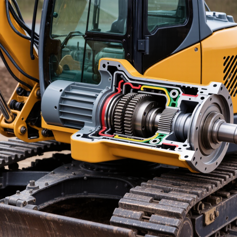
A Mini Final Drive is the compact power unit that moves a mini excavator’s track. It combines a hydraulic motor, reduction gears, bearings, seals, and a planetary gearbox. Hydraulic oil enters the motor and creates rotational force. The gearbox then reduces speed while multiplying torque. That torque reaches the sprocket and pulls the track around the undercarriage.

The principle sounds simple. It is not.

Off-Highway Research’s global construction equipment reports consistently identify compact excavators as an important growth segment, supported by urban projects, landscaping, utilities, and rental fleets. Research and Markets also highlights rising demand for compact construction equipment where access and transport costs matter. These trends place greater pressure on final drives. Operators expect smooth travel, strong pushing force, and dependable performance in narrow spaces.

A reliable Mini Final Drive must handle shock loads, abrasive soil, heat, and repeated direction changes. A dry sprocket may indicate a seal problem. Metallic oil can suggest internal gear or bearing wear. Small signs matter. Manufacturer service manuals remain the strongest reference for oil grade, pressure limits, and replacement procedures. ISO standards help define machinery safety and terminology, but they do not replace model-specific instructions.

This article explains how the drive converts hydraulic flow into track movement. It also examines torque, gear reduction, lubrication, common failures, and maintenance checks. Some market estimates vary because suppliers classify compact equipment differently. That limitation deserves attention. Field conditions vary even more. A clean workshop test cannot fully represent a muddy trench, a steep ramp, or an overloaded trailer. Understanding those gaps leads to better diagnosis and safer decisions.
What Is a Mini Final Drive and How Does It Work?

Mini Final Drive: Definition, Purpose, and Main Components

What Is a Mini Final Drive and How Does It Work?

A mini final drive is a compact drive unit used in small tracked machines. It transfers hydraulic motor power to the track sprocket. Its main purpose is simple: reduce rotational speed and increase turning torque. This allows a compact excavator to climb, turn, and work on uneven ground without demanding excessive hydraulic pressure.

The unit usually contains a hydraulic motor, planetary reduction gears, bearings, seals, and a strong outer housing. Some designs also include a hydraulic parking brake. Pressurized oil enters the motor and turns an internal rotor. That rotation passes through the sun gear, planet gears, and ring gear. The planetary system multiplies torque before the output shaft turns the sprocket. The track then moves through the ground.

Small parts matter greatly. A damaged seal can let oil escape and allow dirt to enter. Worn bearings may create a low grinding sound near the track. I have found that operators often notice slow movement before they notice unusual noise. That observation can be useful, but it is not proof of final drive failure. Low hydraulic flow, a restricted filter, or track tension can create similar symptoms. Checking oil level, leakage, temperature, and sprocket movement gives a more reliable assessment. A warm housing is normal after heavy work; excessive heat is not. Even experienced technicians can misjudge the cause without testing the hydraulic circuit.

How Power Flows Through a Mini Final Drive

A mini final drive converts hydraulic pressure into controlled track movement. Oil from the main pump enters a hydraulic motor inside the drive. The motor spins quickly, but its torque remains limited. A planetary gearbox then reduces speed and multiplies torque. Finally, the output carrier turns the sprocket, pulling the track across the ground.

Typical compact excavator systems operate near 200–350 bar, according to published hydraulic-drive specifications and field service data. Planetary reduction ratios commonly range from 20:1 to 50:1. Technical efficiency often falls between 75% and 90%, depending on oil temperature, load, sealing condition, and bearing friction. These figures are practical ranges, not promises. Real machines are less tidy. A worn bearing can quietly consume power before movement becomes visibly weak. Recent compact-equipment market reports from Off-Highway Research also show continuing demand for small excavators, making final-drive reliability increasingly important in high-cycle applications.

Tips: Check the travel speed on both tracks. Unequal movement may indicate internal leakage, restricted flow, or gear wear. Inspect drain oil for metallic particles, and measure case-drain flow during a warm test. ISO 4413 guidance supports controlled hydraulic maintenance, but field judgement still matters. I would not diagnose a failing drive from noise alone; a loose track, damaged sprocket, or contaminated oil can sound remarkably similar.

What Is a Mini Final Drive and How Does It Work?

A mini final drive transfers power from the hydraulic motor or gearbox to the wheel or track sprocket while reducing speed and increasing torque. The example below uses a 100 N·m input at 1,800 rpm, two reduction stages, and approximately 95% efficiency per stage.

With a 3:1 first-stage reduction and a 4:1 second-stage reduction, output speed falls to about 150 rpm while calculated output torque rises to approximately 1,083 N·m. Power decreases slightly because of normal gear friction and bearing losses; in this example, output power is approximately 17.0 kW from an input of approximately 18.8 kW.

Key Operating Principles of a Mini Final Drive

What Is a Mini Final Drive and How Does It Work?

A mini final drive is a compact gearbox that transfers motor power to a machine’s track or wheel. It reduces speed and increases usable torque at the output shaft. In tracked equipment, hydraulic fluid turns a hydraulic motor inside the drive assembly. The motor then rotates a sun gear, which drives several planetary gears. These gears rotate inside a fixed ring gear. Their carrier delivers slower, stronger rotation to the sprocket or wheel.

Key Operating Principles of a Mini Final Drive

Gear reduction controls the balance between travel speed and pulling force. A higher reduction ratio usually produces more torque but lowers travel speed. Planetary gearing also spreads the load across several gears. This arrangement keeps the housing compact and supports heavy working forces. The oil inside the housing lubricates gear teeth and carries heat away from contact surfaces. Clearances matter. Excessive clearance can cause noise, vibration, and uneven wear.

In practical maintenance, I check oil color, metal particles, seal condition, and unusual housing temperature. A warm case may be normal after continuous digging, but a sharp temperature rise needs investigation. Dirt around a damaged seal can enter quickly, especially on wet job sites. Operators should avoid sudden direction changes under heavy load. That habit stresses gears and bearings. No inspection is perfect. A quiet drive can still hide internal pitting, so operating hours and load history deserve attention. Misalignment may also appear only when the machine carries weight.

Common Types and Applications of Mini Final Drives

What Is a Mini Final Drive and How Does It Work?

A mini final drive is a compact gearbox that delivers torque to a machine’s wheel, track, or working attachment. It receives power from a hydraulic motor or electric motor. Internal gears reduce speed and increase turning force. This allows small machines to move steadily under heavy loads. Planetary final drives are common because several gears share the load. Their compact design also fits narrow chassis spaces.

Other common types include spur gear, helical gear, and worm-drive units. Spur gears are simple and efficient, but they can produce more noise. Helical gears run more smoothly and handle continuous work well. Worm drives offer strong reduction, although they may create more heat. These units appear in mini excavators, tracked carriers, compact loaders, lifting equipment, agricultural machines, and mobile robots. In field repairs, I have seen small alignment errors cause unusual wear. The cause is not always the gearbox itself. Mounting stress, poor lubrication, or incorrect chain tension may be responsible.

Tips: Check the rated torque, reduction ratio, and mounting dimensions before purchase. Confirm the required oil type and service interval. Inspect seals after muddy or dusty work. Listen for clicking, grinding, or rising operating temperature. A slightly oversized drive may improve durability, but it can increase weight and cost. That trade-off deserves careful review.

Maintenance Factors and Typical Failure Symptoms

What Is a Mini Final Drive and How Does It Work?

A mini final drive is a compact gear reduction unit used in small tracked machines. It transfers motor torque to the track sprocket. Inside, planetary gears reduce speed and increase pulling force. The housing also protects the gears, bearings, and seals from dust, mud, and water. A final drive may look simple outside. Internally, it demands precise lubrication and alignment.

Maintenance begins with checking the oil level and condition at recommended service intervals. Dark oil, metallic particles, or a burnt smell may indicate internal wear. Use the specified lubricant, because incorrect viscosity can increase heat and gear friction. Clean around the fill and drain plugs before opening them. Otherwise, grit can enter the housing. Inspect the sprocket bolts, mounting area, and shaft seal for looseness or wet oil marks.

Watch for symptoms during operation. A whining, grinding, or clicking sound can suggest damaged gears or bearings. Excessive heat around one drive often points to low oil, overloading, or restricted movement. Track speed may become uneven. The machine may also pull to one side, move slowly, or lose power under load. Oil leaking near the sprocket should not be ignored. Small leaks become expensive failures. A common mistake is replacing only the seal without checking shaft wear. That repair may fail again. Record noise, temperature, oil appearance, and operating conditions before removing the unit. These details help confirm the fault instead of guessing.

What Is a Mini Final Drive and How Does It Work? - Maintenance Factors and Typical Failure Symptoms

Data Dimension Technical Information Maintenance or Diagnostic Importance
Definition A mini final drive is a compact hydraulic travel motor and planetary reduction gearbox used to drive the track or wheel of a small excavator, mini loader, or other compact tracked machine. It converts hydraulic power into controlled rotary motion and increases output torque while reducing rotational speed.
Main Power Path Hydraulic pump → travel control valve → hydraulic motor → planetary gear set → output hub or sprocket → track or wheel. A fault in any part of this path can cause weak travel, abnormal noise, overheating, or complete loss of movement.
Hydraulic Motor The motor uses pressurized hydraulic oil to create rotary motion. Depending on the design, it may be a fixed-displacement or variable-displacement motor. Low pressure, restricted flow, contaminated oil, worn internal parts, or damaged seals can reduce torque and travel speed.
Planetary Gearbox A sun gear, planet gears, planet carrier, and ring gear provide speed reduction and torque multiplication in a compact housing. Gear wear, broken teeth, damaged bearings, or insufficient lubrication can produce grinding, knocking, metal debris, and loss of drive.
Output Hub and Sprocket The final reduction stage transfers torque to the sprocket or wheel hub, which engages the track or propels the machine. Loose fasteners, worn splines, damaged bearings, or sprocket wear may cause backlash, uneven travel, or track derailment.
Reduction Ratio The planetary stage typically reduces motor speed substantially to provide the high torque required for track movement. The exact ratio varies by machine and drive configuration. The correct ratio and replacement parts must match the machine’s hydraulic flow, pressure, weight, and travel requirements.
Gear Oil The gearbox requires the lubricant grade and fill quantity specified for the particular drive assembly. Oil protects gears and bearings from friction, heat, and wear. Check the level on firm, level ground and inspect for a milky appearance, burnt odor, metal particles, or water contamination.
Hydraulic Oil Condition Hydraulic oil should be clean, correctly specified, and maintained within the equipment manufacturer’s viscosity and contamination limits. Dirty or degraded oil can damage motor surfaces, valves, bearings, and seals, accelerating internal leakage and performance loss.
External Leakage Oil may escape from the motor shaft seal, housing joint, drain plug, hydraulic fittings, or hose connections. Clean the area before inspection, identify the source, and repair leaks promptly. Low oil levels can lead to bearing and gear failure.
Overheating Excessive temperature may result from overloaded operation, restricted hydraulic flow, brake drag, low lubricant level, worn bearings, or internal leakage. Stop and investigate persistent overheating. Continued operation can damage seals, reduce lubricant viscosity, and accelerate gear wear.
Typical Noise: Whine A rising whine may indicate gear mesh wear, bearing wear, incorrect lubrication, or hydraulic motor cavitation. Compare the noise during forward and reverse travel, check oil condition, and verify hydraulic supply before dismantling the drive.
Typical Noise: Knocking or Grinding Knocking or grinding can be associated with broken gear teeth, excessive backlash, damaged bearings, loose components, or severe lubrication failure. Avoid continued heavy operation. Inspect the drained oil and magnetic plug for metal fragments and perform a mechanical inspection.
Weak or Slow Travel Possible causes include low hydraulic pressure or flow, worn motor components, internal leakage, a restricted filter, an incorrectly adjusted valve, or a mechanical gearbox problem. Test hydraulic pressure and flow according to the service procedure before replacing the final drive.
One-Side Travel Difference If one track moves slower or lacks torque, the cause may be a faulty drive motor, hydraulic control issue, unequal track tension, undercarriage resistance, or internal gearbox damage. Check both hydraulic circuits and compare track tension, sprocket condition, rollers, idlers, and travel motor behavior.
Track Does Not Move A complete loss of movement may be caused by a disconnected hose, blocked passage, failed motor, damaged planetary gears, seized bearings, failed brake release, or insufficient hydraulic pressure. Secure the machine, relieve hydraulic pressure safely, and diagnose the hydraulic and mechanical systems separately.
Oil Contamination Water, dirt, or metallic particles in gear oil can enter through damaged seals, open service points, condensation, or component wear. Replace contaminated lubricant, locate the ingress source, inspect internal parts, and follow proper cleaning procedures.
Track Tension Incorrect tension increases load on the sprocket, idler, rollers, bearings, and final drive. Excessive slack may promote derailment, while excessive tightness increases resistance. Inspect and adjust tension according to the machine’s service specification and operating conditions.
Routine Inspection Inspect for leaks, loose mounting bolts, damaged hoses, unusual noise, overheating, sprocket wear, track condition, and abnormal movement. Daily or pre-operation checks can identify small faults before they develop into motor, gearbox, or undercarriage failures.
Service Interval Gear-oil changes, filter replacement, hose inspection, and seal checks must follow the equipment-specific service schedule and operating environment. Heavy loads, abrasive soil, water exposure, high ambient temperature, and frequent travel may require more frequent inspections or servicing.
Safe Diagnostic Practice Hydraulic systems can retain high pressure, and tracks can move unexpectedly. Mechanical inspection may require lifting or supporting heavy components. Park securely, lower attachments, isolate energy sources, relieve hydraulic pressure, use approved supports, and follow the applicable service manual.
© Copyright - Pro Tool & Supply - Site by SVM E-Marketing Solutions - Sitemap - Privacy policy
