Sales & Rental of Construction | Industrial Equipment & Supplies

What Are Milled Parts and How Are They Made?

Milled Parts are components shaped by removing material from a solid workpiece. Unlike molded products, they begin as blocks, plates, or bars of metal, plastic, or composite material. A rotating cutting tool removes small chips until the required geometry appears. This method can create flat faces, pockets, slots, holes, and curved surfaces with impressive accuracy. The process often starts with a CAD model, but the model is only a plan. Real production also depends on material behavior, machine condition, tooling, and operator judgment.

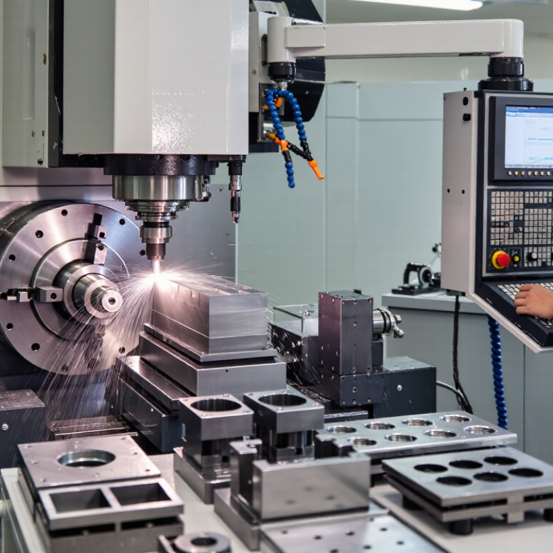
A machinist or engineer converts the design into CAM toolpaths. These instructions control cutting speed, feed rate, depth, and tool movement. The workpiece is secured in a vise, fixture, or custom holding system. Then, a CNC milling machine removes material through several operations. Roughing quickly clears excess stock. Finishing passes refine edges and surface texture. Coolant may reduce heat and improve tool life. Small details matter. A loose fixture can shift a part by a fraction of a millimeter.

After machining, technicians inspect critical dimensions with calipers, micrometers, gauges, or coordinate measuring machines. They may also check burrs, tool marks, and surface finish. Milled Parts are not automatically perfect because a digital file exists. Tool wear, thermal expansion, and incorrect measurement can create unexpected results. That reality deserves attention. Good manufacturing combines automation with experienced review, careful documentation, and honest process improvement. This article explains how Milled Parts are designed, machined, inspected, and refined for dependable use.
What Are Milled Parts and How Are They Made?

What Are Milled Parts and What Makes Them Different?

Milled parts are made by removing material with rotating cutting tools. The workpiece stays clamped while cutters travel across its surfaces. This differs from turned parts, where the stock rotates against a stationary tool. It also differs from molded parts, which begin as liquid or softened material. The result is usually a rigid component with defined pockets, holes, steps, and curved profiles. That distinction is easy to blur. The machine removes material, not just shapes it.

What makes milled parts different is their balance between design freedom and process discipline. A five-axis machine can reach angled faces and reduce repeated setups. A simple three-axis machine may still produce excellent plates, brackets, and housings. Material changes the cutting strategy. Aluminum cuts quickly, while stainless steel demands slower feeds, sharper tooling, and better heat control. Surface finish, tolerance, burrs, and clamping marks all affect the usable part. Small detail. It can decide whether assembly feels smooth or frustrating.

Industry data shows why this capability matters. The World Robotics 2024 report recorded 4,281,585 industrial robots operating worldwide in 2023, supporting more automated machining cells. UNIDO’s 2024 industrial statistics placed global manufacturing value added at roughly 16 trillion dollars in 2023. These figures indicate scale, not guaranteed quality. In practice, quality still depends on inspection, tool wear control, and a clear drawing. I have seen production plans fail because a beautiful model ignored cutter access. A milled part can be accurate and still be poorly designed. That is the uncomfortable part.

Which Materials and Designs Are Suitable for Milling?

Milled parts are shaped by removing material with rotating cutting tools. The process suits many materials, but each one changes the machining strategy.

Aluminum is popular because it cuts quickly and offers a strong, lightweight result.

Steel provides greater strength, although it usually needs slower cutting speeds and better heat control.

Brass machines cleanly and can produce sharp details.

Engineering plastics are useful for low-friction or electrically insulating components, but thin sections may deform during clamping.

Titanium can be milled accurately, yet it demands rigid equipment, careful tool selection, and controlled temperatures.

Material choice should follow the part’s real working conditions. A bracket exposed to vibration may need steel, while a lightweight housing may benefit from aluminum. Plastics can work well for prototypes, but they may expand with heat.

That detail is easy to miss. It can change the final fit.

Good milling designs give the cutter clear access. Internal corners should include a radius because round tools cannot create perfectly sharp corners.

Deep pockets, tall thin walls, and narrow slots increase vibration and tool deflection. Keep walls thick enough for stable cutting, and avoid unnecessary details that add time without improving function.

Through-holes are often simpler than blind holes, especially when chips must escape. A practical designer also considers clamping surfaces and burr removal.

Milled surfaces can look precise, but their finish still depends on tool condition, material behavior, and setup quality.

I would not trust a drawing alone. A small test cut can reveal problems before full production.

How Are Milled Parts Designed and Programmed?

Designing milled parts begins with a precise digital model. Engineers define the part’s shape, dimensions, material, and functional surfaces. A machinist also studies how cutting tools will reach each feature. Clear datum references guide the setup and reduce alignment errors. Tolerances should match real performance needs, not simply appear impressive on a drawing. Small holes, deep pockets, and thin walls can create serious machining challenges. Sometimes, the first design is not practical.

After approval, the model moves into computer-aided manufacturing software. The programmer selects tools, workholding methods, cutting directions, and machining operations. Roughing paths remove most material quickly. Finishing paths create the final surface and edge condition. Tool diameter, spindle speed, feed rate, and cutting depth must work together. A digital simulation can reveal collisions and excessive tool movement. Still, software does not understand every real-world vibration or fixture weakness.

Before production, a qualified machinist reviews the program and setup plan. Trial cutting may expose unexpected deflection, heat, or chip evacuation problems. Measurements from the first part provide valuable evidence. If a wall measures slightly thin, the programmer may adjust the toolpath or revise the model. That feedback improves both accuracy and repeatability. Experienced teams document these changes carefully. Yet no process is perfect. Good programming leaves room for inspection, correction, and practical judgment.

What Are Milled Parts and How Are They Made? - How Are Milled Parts Designed and Programmed?

Design or Manufacturing Dimension What It Means Typical Data or Practice Effect on the Milled Part
Part Definition A milled part is produced by removing material from a solid workpiece with rotating cutting tools controlled by a machine tool. Common operations include facing, slotting, pocketing, drilling, contouring, and 3D surface machining. The final geometry is created through subtractive manufacturing rather than by depositing or molding material.
CAD Model A computer-aided design model defines the part’s shape, dimensions, holes, pockets, fillets, and reference features. The model is commonly created as a parametric 3D solid and supplemented by drawings, tolerances, material notes, and surface requirements. A complete and consistent model reduces ambiguity during process planning and programming.
Material Selection The workpiece material influences cutting conditions, tool selection, heat generation, and finishing requirements. Frequently machined materials include aluminum alloys, steels, stainless steels, titanium alloys, brass, engineering plastics, and nickel-based alloys. Hardness, thermal conductivity, and abrasiveness affect cycle time, tool wear, and achievable surface quality.
Datum and Workholding Datums establish the coordinate reference system, while workholding keeps the stock secure during cutting. Typical methods include vises, clamps, fixtures, soft jaws, vacuum fixtures, and multi-sided setups. Accurate locating and adequate rigidity help control position, flatness, vibration, and repeatability.
Machine Configuration The machine’s axes and spindle capacity determine which features can be reached and how many setups are required. Three-axis machines control X, Y, and Z linear motion; four- and five-axis machines add rotary positioning or simultaneous tool motion. Additional axes can reduce repositioning and improve access to complex surfaces, but they require more advanced programming and verification.
Tool Selection Cutting tools are selected according to feature size, material, depth, accessibility, and required finish. Common tools include face mills, end mills, ball-nose cutters, drills, chamfer tools, and reamers. Tool diameter, flute count, corner radius, coating, and stick-out influence accuracy, chip evacuation, and productivity.
Cutting Parameters Programming requires values that control how fast the tool rotates, advances, and engages the material. Key variables are spindle speed, feed rate, depth of cut, radial width of cut, coolant method, and material-specific cutting data. Balanced parameters help prevent excessive tool wear, chatter, overheating, burrs, and poor surface finish.
CAM Toolpaths Computer-aided manufacturing software converts the CAD design into a sequence of machining movements. Typical strategies include adaptive clearing, roughing, finishing, contouring, drilling cycles, rest machining, and 3D surface finishing. The selected strategy determines material-removal efficiency, tool engagement, cycle time, and surface appearance.
Post-Processing A post-processor translates CAM toolpaths into machine-specific numerical control instructions. The output may include tool changes, spindle commands, feed commands, coordinate movements, coolant commands, and safety lines. Correct post-processing is essential because different machine controls interpret code and cycles differently.
Simulation and Verification The programmed process is checked before machining to identify collisions, over-travel, gouging, and remaining stock. Verification may include toolpath simulation, machine-motion simulation, stock comparison, and code review. Early detection of errors lowers the risk of fixture damage, tool breakage, scrap, and machine downtime.
Tolerance Planning Tolerances define the permitted variation in dimensions, form, orientation, and feature location. Unspecified dimensions commonly follow a drawing standard or general tolerance note; critical features receive individual limits or geometric tolerances. Tighter tolerances may require additional finishing passes, controlled temperature, inspection, or multiple setups.
Surface Finish Surface finish describes the texture left by the cutting process and any later finishing operation. It is often specified using roughness parameters such as Ra, with the required value depending on function and application. Toolpath overlap, feed rate, tool condition, machine rigidity, and finishing operations affect the measured result.
Inspection Inspection confirms that the finished component meets dimensional, geometric, and visual requirements. Methods include calipers, micrometers, height gauges, pin gauges, surface testers, optical systems, and coordinate measuring machines. Inspection results support process adjustment, acceptance decisions, and traceable quality records.
Design for Milling Design choices can make a part easier, faster, and more reliable to machine. Useful practices include providing tool access, avoiding unnecessarily deep narrow pockets, adding internal corner radii, minimizing setups, and specifying only necessary tight tolerances. A milling-friendly design can reduce tooling complexity, machining time, risk of vibration, and overall manufacturing cost.
Process Summary: CAD model → datum and setup planning → tool selection → CAM toolpaths → post-processing → simulation → CNC milling → inspection.

How Does the Milling Process Shape Each Part?

Milled parts are components shaped by removing material from a solid block. A milling cutter rotates while the workpiece stays clamped or moves precisely. The tool follows programmed paths across metal, plastic, or composite stock. Each pass changes the part’s geometry. A roughing pass removes bulk material quickly. Finishing passes create the final surfaces, edges, and pockets. The result depends on more than the drawing. Tool stiffness, workholding, heat, and cutter condition all influence the shape.

A flat end mill can produce a level face, while a ball-nose cutter forms curved contours. Drills create holes, but milling can enlarge, position, or interpolate them accurately. Three-axis machines handle many prismatic shapes. More axes can reach angled surfaces without repeated clamping. That matters because every reclamping introduces possible alignment error. Tight corners need smaller tools, yet small tools bend more easily. Cutting speed, feed rate, and step-over must suit the material. Too much heat may distort thin walls. Too little feed can rub instead of cut.

Inspection reveals whether the process truly matched the design. Operators may check dimensions with calibrated gauges, probes, or coordinate measuring equipment. Surface finish also deserves attention. A part can measure correctly and still perform poorly. I have seen a tiny burr interfere with assembly, despite otherwise accurate machining. Process review can expose the cause. Adjusting tool paths, supports, or cutting conditions may improve the next part. Not every mark is a defect, but every unexplained mark deserves investigation.

How Are Milled Parts Inspected and Finished?

Milled parts are inspected before finishing can hide important evidence. Operators begin by cleaning chips, oil, and dust from each surface. They check dimensions against the engineering drawing and its stated tolerances. Calipers suit general measurements, while micrometers measure tighter features with greater control. A coordinate measuring machine can verify hole positions, profiles, and complex three-dimensional surfaces.

Visual inspection also matters. Under angled light, inspectors look for burrs, chatter marks, scratches, tool lines, and incomplete corners. Surface roughness may be measured with a portable tester when the specification requires it. Inspectors should record temperature, equipment identification, and measurement results. Small temperature changes can affect tight measurements. That detail is easy to overlook.

Finishing starts with careful deburring and edge breaking. Technicians remove sharp fragments without changing critical geometry. Parts may then receive bead blasting, polishing, anodizing, plating, or protective coating, depending on material and use. Each process can alter color, thickness, friction, or dimensional fit. Masking threads and precision bores helps prevent costly rework. After finishing, inspectors repeat critical checks and examine coating coverage, adhesion, and visible damage. Inspection is not flawless. A rushed setup or unclear datum can produce confident but incorrect results. For that reason, a second review is valuable, especially when the first measurement seems unusually perfect.

How Are Milled Parts Inspected and Finished?

The chart shows the permitted deviation for linear dimensions from 30 to 120 mm under ISO 2768-1 general tolerance classes. Finished milled parts are commonly verified with calipers, micrometers, gauges, or coordinate measuring machines before surface finishing and final approval.

Reference: ISO 2768-1 general tolerances for linear dimensions.

© Copyright - Pro Tool & Supply - Site by SVM E-Marketing Solutions - Sitemap - Privacy policy
