- Products
- Air Compressors & Air Tools
- Climate Control
- Compaction Equipment
- Concrete Cutting Tools & Equipment
- Concrete and Masonry
- Demolition & Excavation
- Electrical & Mechanical
- Fasteners and Anchoring Adhesives
- Floor Protection
- Generators and Welders
- Hand Tools
- Heaters
- Janitorial and Office Supplies
- Jobsite Protection
- Ladders & Storage
- Lighting & Lighting Accessories
- Man Lifts
- Material Handling Equipment
- Power Tools
- Pressure Washers & Pumps
- Safety Gear
- Safety Products
- Saws
- Surface Preparation
- SEASONAL PRODUCTS
- Rentals
- Air Compressor and Air Tool Rentals
- Climate Control Rental
- Compaction Rentals
- Concrete Equipment Rentals
- Demolition & Excavation Equipment Rentals
- Concrete Floor Grinder Rentals
- General Construction Equipment Rentals
- Generator Rentals and Welder Rentals
- Heater Rentals
- Light Tower Rentals
- Man Lift Rentals in Massachusetts and Rhode Island
- Material Handling Equipment Rentals
- Pressure Washer & Pump Rentals
- Saw Rentals in New England
- SEASONAL PRODUCTS
- Products
- Air Compressors & Air Tools
- Climate Control
- Compaction Equipment
- Concrete Cutting Tools & Equipment
- Demolition & Excavation
- Electrical & Mechanical
- Floor Protection
- Generators and Welders
- Construction Heaters
- Construction Ladders, Staging, & Storage
- Construction Lighting
- Man Lifts
- Material Handling Equipment
- Industrial Janitorial and Office Supplies
- Pressure Washers & Pumps
- Construction Safety Products
- Construction Safety Gear
- Surface Preparation
- Building Protection
- Diesel Accessories
- Zero Emissions
- Rentals
- Air Compressor and Air Tool Rentals
- Climate Control Rental
- Compaction Rentals
- Concrete Equipment Rental
- Demolition & Excavation Equipment Rental
- General Construction Equipment Rental
- Generator Rentals and Welder Rentals
- Construction Heaters Rental
- Light Tower Rentals
- Man Lift Rentals
- Material Handling Equipment Rental
- Pressure Washer & Pump Rentals
- Saw Rentals in New England
- Concrete Floor Grinder Rentals
- Zero Emissions Rentals
- Repairs & Used
- Parts
- Blog
- Services
- Resources
- About Us
- Contact Us
Sales & Rental of Construction | Industrial Equipment & Supplies


How to Wire an LED Rocker Switch?
Wiring a Led Rocker Switch can look simple, but the small terminals often cause expensive mistakes. An illuminated switch may control lights, fans, pumps, or other low-voltage accessories. Its internal design is not always identical. Some models use two terminals, while others include separate power, load, ground, and illumination connections.
A reliable installation begins with the switch diagram, not guesswork. Disconnect the power source before touching any wire. Inspect the terminal labels, then compare them with the manufacturer’s instructions. A multimeter can confirm continuity when the switch is off and on. This quick test often reveals whether the chosen terminal controls the load or only the indicator light.
Keep the circuit protected. A correctly sized fuse should sit close to the battery or power supply. Use wire suitable for the expected current, and secure every connection with a crimp terminal, soldered joint, or approved connector. Loose copper strands can create heat behind the panel. That detail is easy to miss.
The wiring path usually runs from positive power through the fuse, into the switch, and onward to the accessory. The accessory then returns to a suitable ground. Some illuminated switches need a separate ground wire for the lamp. Others illuminate only when the load is powered. Check this carefully.
There is no universal color code. Red is commonly positive, but installers should never trust color alone. Test before energizing. A wiring diagram may seem obvious, yet one reversed terminal can leave the accessory working while the light stays dark. That is a useful reminder: confirm each connection instead of relying on assumptions.
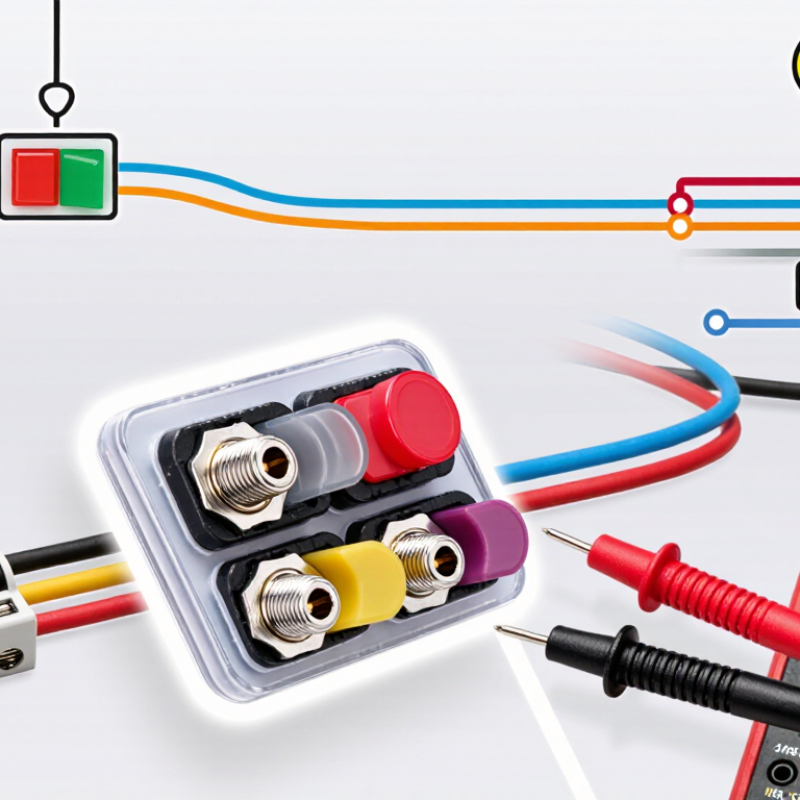
Table of Contents [Hide]
Identify the LED Rocker Switch Terminals and Circuit Requirements
How to Wire an LED Rocker Switch?
Before wiring an LED rocker switch, identify every terminal carefully. Common terminals include power input, load output, ground, and LED negative. Some switches combine the LED ground with the circuit ground. Others use separate LED terminals. Never assume the layout is universal. Check the terminal markings or the manufacturer’s wiring diagram.
The circuit must match the switch’s voltage and current ratings. A 12-volt switch should not connect directly to a higher-voltage supply. Connect the power terminal to the fused positive source. Connect the load terminal to the device’s positive wire. Attach the ground terminal to a clean chassis point or the supply negative. The LED may need its own positive and negative connections. Confirm polarity before applying power. The lamp stays dark.
Use a fuse close to the power source. Select its rating according to the load and wire capacity, not personal preference. I once tested a switch without checking its internal LED polarity. The switch worked, but the indicator did not. That small mistake cost extra time. Do not guess. Use a multimeter to identify continuity and terminal behavior, especially with SPDT switches. Keep wire insulation away from sharp panel edges. A loose crimp can create heat later. Recheck every connection with the power disconnected, then test the circuit under its normal load.

© Copyright - Pro Tool & Supply - Site by SVM E-Marketing Solutions - Sitemap
- Privacy policy