- Products
- Air Compressors & Air Tools
- Climate Control
- Compaction Equipment
- Concrete Cutting Tools & Equipment
- Concrete and Masonry
- Demolition & Excavation
- Electrical & Mechanical
- Fasteners and Anchoring Adhesives
- Floor Protection
- Generators and Welders
- Hand Tools
- Heaters
- Janitorial and Office Supplies
- Jobsite Protection
- Ladders & Storage
- Lighting & Lighting Accessories
- Man Lifts
- Material Handling Equipment
- Power Tools
- Pressure Washers & Pumps
- Safety Gear
- Safety Products
- Saws
- Surface Preparation
- SEASONAL PRODUCTS
- Rentals
- Air Compressor and Air Tool Rentals
- Climate Control Rental
- Compaction Rentals
- Concrete Equipment Rentals
- Demolition & Excavation Equipment Rentals
- Concrete Floor Grinder Rentals
- General Construction Equipment Rentals
- Generator Rentals and Welder Rentals
- Heater Rentals
- Light Tower Rentals
- Man Lift Rentals in Massachusetts and Rhode Island
- Material Handling Equipment Rentals
- Pressure Washer & Pump Rentals
- Saw Rentals in New England
- SEASONAL PRODUCTS
- Products
- Air Compressors & Air Tools
- Climate Control
- Compaction Equipment
- Concrete Cutting Tools & Equipment
- Demolition & Excavation
- Electrical & Mechanical
- Floor Protection
- Generators and Welders
- Construction Heaters
- Construction Ladders, Staging, & Storage
- Construction Lighting
- Man Lifts
- Material Handling Equipment
- Industrial Janitorial and Office Supplies
- Pressure Washers & Pumps
- Construction Safety Products
- Construction Safety Gear
- Surface Preparation
- Building Protection
- Diesel Accessories
- Zero Emissions
- Rentals
- Air Compressor and Air Tool Rentals
- Climate Control Rental
- Compaction Rentals
- Concrete Equipment Rental
- Demolition & Excavation Equipment Rental
- General Construction Equipment Rental
- Generator Rentals and Welder Rentals
- Construction Heaters Rental
- Light Tower Rentals
- Man Lift Rentals
- Material Handling Equipment Rental
- Pressure Washer & Pump Rentals
- Saw Rentals in New England
- Concrete Floor Grinder Rentals
- Zero Emissions Rentals
- Repairs & Used
- Parts
- Blog
- Services
- Resources
- About Us
- Contact Us
Sales & Rental of Construction | Industrial Equipment & Supplies


How to Choose an Industrial Chain Conveyor?
Choosing an Industrial Chain Conveyor is rarely as simple as comparing prices or motor ratings. The right system must match your product, floor layout, operating speed, and maintenance capacity. A conveyor carrying hot castings needs different protection than one moving packaged food products. Chain type, flight design, frame material, and drive arrangement all influence performance.
Start with the load. Measure product weight, dimensions, surface condition, and spacing between items. Then examine the route, including inclines, transfers, washdown areas, and restricted access points. A practical evaluation should also consider chain tension, sprocket wear, guarding, noise, and emergency stops. These details often determine whether the conveyor runs smoothly or creates daily delays.
Real operating experience matters. Ask suppliers for test data, installation references, and clear maintenance intervals. If possible, inspect a similar conveyor in service. Watch how operators clean it, adjust the chain, and remove damaged components. Specifications can look impressive on paper. Reality is less polite.
Avoid choosing from catalog numbers alone. A higher load rating does not automatically mean better value. Oversized equipment may consume more energy and complicate repairs. Undersized equipment may suffer from stretch, shock loading, and premature failure. Your first assumptions may be wrong. Recheck them against peak loads, not average conditions.
This guide explains the main selection factors and the questions worth asking before purchase. It also highlights common design compromises, so your final decision remains practical, safe, and supportable over many years.
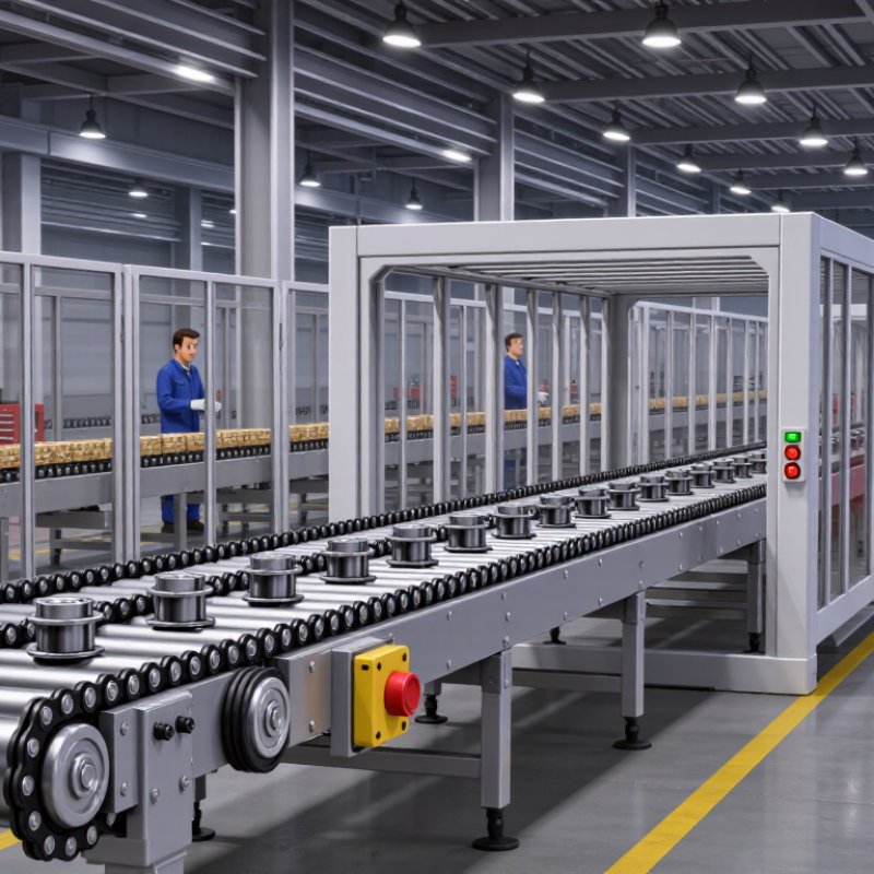
Table of Contents [Hide]
Define Load, Throughput, and Duty Cycle with Capacity = Load × Rate
How to Choose an Industrial Chain Conveyor?
Start with three measurable values: load, throughput, and duty cycle. Load means the total weight carried by each chain attachment, pallet, or carrier. Include the product, fixture, and packaging. Throughput is the required movement rate, such as 12 carriers per minute. A practical first estimate is Capacity = Load × Rate.
80 kilograms × 12 carriers per minute
= 960 kilograms per minute
= 960 kilograms per minute
Keep the units consistent.
Duty cycle describes how long and how often the conveyor operates. A line running eight hours continuously needs different performance from one running ten minutes per hour. Consider starts, stops, accumulation, inclines, temperature, and uneven loading. These details affect chain tension, motor heating, wear, and frame stiffness. The simple equation helps, but it is not complete. Real systems are rarely so tidy.
Tips: Measure actual product weight, not the catalog estimate. Record peak throughput during shift changes. Check whether the load sits centrally or pulls sideways. Add a reasonable design margin, but avoid excessive oversizing, which can increase cost and impact energy use. Test the heaviest product under the fastest planned rate. Review the calculation after installation; operators often reveal conditions missed during design. A conveyor can meet the average capacity and still fail during frequent starts. That is where careful observation matters.

© Copyright - Pro Tool & Supply - Site by SVM E-Marketing Solutions - Sitemap
- Privacy policy