- Products
- Air Compressors & Air Tools
- Climate Control
- Compaction Equipment
- Concrete Cutting Tools & Equipment
- Concrete and Masonry
- Demolition & Excavation
- Electrical & Mechanical
- Fasteners and Anchoring Adhesives
- Floor Protection
- Generators and Welders
- Hand Tools
- Heaters
- Janitorial and Office Supplies
- Jobsite Protection
- Ladders & Storage
- Lighting & Lighting Accessories
- Man Lifts
- Material Handling Equipment
- Power Tools
- Pressure Washers & Pumps
- Safety Gear
- Safety Products
- Saws
- Surface Preparation
- SEASONAL PRODUCTS
- Rentals
- Air Compressor and Air Tool Rentals
- Climate Control Rental
- Compaction Rentals
- Concrete Equipment Rentals
- Demolition & Excavation Equipment Rentals
- Concrete Floor Grinder Rentals
- General Construction Equipment Rentals
- Generator Rentals and Welder Rentals
- Heater Rentals
- Light Tower Rentals
- Man Lift Rentals in Massachusetts and Rhode Island
- Material Handling Equipment Rentals
- Pressure Washer & Pump Rentals
- Saw Rentals in New England
- SEASONAL PRODUCTS
- Products
- Air Compressors & Air Tools
- Climate Control
- Compaction Equipment
- Concrete Cutting Tools & Equipment
- Demolition & Excavation
- Electrical & Mechanical
- Floor Protection
- Generators and Welders
- Construction Heaters
- Construction Ladders, Staging, & Storage
- Construction Lighting
- Man Lifts
- Material Handling Equipment
- Industrial Janitorial and Office Supplies
- Pressure Washers & Pumps
- Construction Safety Products
- Construction Safety Gear
- Surface Preparation
- Building Protection
- Diesel Accessories
- Zero Emissions
- Rentals
- Air Compressor and Air Tool Rentals
- Climate Control Rental
- Compaction Rentals
- Concrete Equipment Rental
- Demolition & Excavation Equipment Rental
- General Construction Equipment Rental
- Generator Rentals and Welder Rentals
- Construction Heaters Rental
- Light Tower Rentals
- Man Lift Rentals
- Material Handling Equipment Rental
- Pressure Washer & Pump Rentals
- Saw Rentals in New England
- Concrete Floor Grinder Rentals
- Zero Emissions Rentals
- Repairs & Used
- Parts
- Blog
- Services
- Resources
- About Us
- Contact Us
Sales & Rental of Construction | Industrial Equipment & Supplies


How to Choose a 15kV 200A Loadbreak Junction in 2026?
Choosing a 15kv 200a Loadbreak Junction in 2026 requires more than matching voltage and current labels. A 15 kV class rating does not mean the connector suits every 15 kV feeder. System grounding, fault duty, insulation diameter, interface type, and installation conditions matter.
IEEE Std 386-2014 remains a key technical reference for separable insulated connectors used on distribution systems. Its requirements address interfaces, dielectric performance, temperature rise, and loadbreak operation. Recent medium-voltage equipment outlooks from MarketsandMarkets also point to continued grid modernization and higher replacement demand. That growth sounds encouraging, but market forecasts cannot replace field verification.
John D. McDonald, IEEE Fellow and power-system specialist, offers a useful selection principle: “Reliability begins with matching the equipment to the system, not the catalog headline.” The quotation is practical, even if it deserves a source check before publication.
A reliable evaluation starts at the cable trench. Measure the cable insulation diameter. Confirm the bushing interface. Check whether 200 A is continuous duty or only a loadbreak rating. Review the available fault current, not merely the nominal voltage. Inspect the elbow parking position, grounding arrangement, and clearance around the junction.
Look closely.
Manufacturers may describe similar products with different test language. A connector passing one test does not automatically satisfy every utility specification. This guide compares electrical ratings, interface compatibility, environmental protection, installation evidence, and supplier documentation. It also considers a less comfortable question: is the selected 15kv 200a Loadbreak Junction genuinely suitable, or merely easy to order?
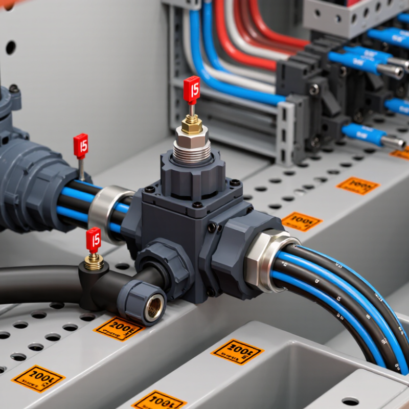
Table of Contents [Hide]
What a 15kV 200A Loadbreak Junction Is
A 15kV 200A loadbreak junction is a medium-voltage connection point designed for controlled switching and cable isolation. It normally links underground distribution cables, transformers, switchgear, or sectionalizing equipment. The 15kV rating identifies its voltage class, not a guaranteed operating voltage under every condition. The 200A rating indicates continuous current capacity under specified installation conditions.
It is not merely a larger cable connector. A qualified junction uses separable interfaces, insulation shielding, and a loadbreak mechanism. IEEE Standard 386 defines key requirements for separable insulated connectors, including electrical performance and interface compatibility. In field work, I check the cable insulation diameter, conductor size, grounding method, and available fault current before selection. A mismatch can create heat, tracking, or difficult disconnection.
Details matter.
The U.S. Energy Information Administration reported average customer interruptions of several hours in recent reliability data, excluding major events. That figure shows why sectionalizing equipment matters during maintenance and faults. The U.S. Department of Energy also identifies distribution resilience as a growing planning priority. Still, current ratings are easy to misunderstand. A 200A junction may require derating in crowded vaults, high ambient temperatures, or grouped installations. I would also verify impulse withstand, fault-duty coordination, operating tools, and clearance requirements. Catalog data alone is not enough; site measurements and the latest utility specifications should control the final choice.

© Copyright - Pro Tool & Supply - Site by SVM E-Marketing Solutions - Sitemap
- Privacy policy