- Products
- Air Compressors & Air Tools
- Climate Control
- Compaction Equipment
- Concrete Cutting Tools & Equipment
- Concrete and Masonry
- Demolition & Excavation
- Electrical & Mechanical
- Fasteners and Anchoring Adhesives
- Floor Protection
- Generators and Welders
- Hand Tools
- Heaters
- Janitorial and Office Supplies
- Jobsite Protection
- Ladders & Storage
- Lighting & Lighting Accessories
- Man Lifts
- Material Handling Equipment
- Power Tools
- Pressure Washers & Pumps
- Safety Gear
- Safety Products
- Saws
- Surface Preparation
- SEASONAL PRODUCTS
- Rentals
- Air Compressor and Air Tool Rentals
- Climate Control Rental
- Compaction Rentals
- Concrete Equipment Rentals
- Demolition & Excavation Equipment Rentals
- Concrete Floor Grinder Rentals
- General Construction Equipment Rentals
- Generator Rentals and Welder Rentals
- Heater Rentals
- Light Tower Rentals
- Man Lift Rentals in Massachusetts and Rhode Island
- Material Handling Equipment Rentals
- Pressure Washer & Pump Rentals
- Saw Rentals in New England
- SEASONAL PRODUCTS
- Products
- Air Compressors & Air Tools
- Climate Control
- Compaction Equipment
- Concrete Cutting Tools & Equipment
- Demolition & Excavation
- Electrical & Mechanical
- Floor Protection
- Generators and Welders
- Construction Heaters
- Construction Ladders, Staging, & Storage
- Construction Lighting
- Man Lifts
- Material Handling Equipment
- Industrial Janitorial and Office Supplies
- Pressure Washers & Pumps
- Construction Safety Products
- Construction Safety Gear
- Surface Preparation
- Building Protection
- Diesel Accessories
- Zero Emissions
- Rentals
- Air Compressor and Air Tool Rentals
- Climate Control Rental
- Compaction Rentals
- Concrete Equipment Rental
- Demolition & Excavation Equipment Rental
- General Construction Equipment Rental
- Generator Rentals and Welder Rentals
- Construction Heaters Rental
- Light Tower Rentals
- Man Lift Rentals
- Material Handling Equipment Rental
- Pressure Washer & Pump Rentals
- Saw Rentals in New England
- Concrete Floor Grinder Rentals
- Zero Emissions Rentals
- Repairs & Used
- Parts
- Blog
- Services
- Resources
- About Us
- Contact Us
Sales & Rental of Construction | Industrial Equipment & Supplies


What Is a Polarization Modulator and How Does It Work?
A Polarization Modulator controls the orientation or ellipticity of light’s electric field. It can switch between horizontal and vertical polarization, rotate a linear state, or create circular polarization. The change may be subtle to the eye. Yet a sensor, optical link, or laboratory instrument can detect it.
In many designs, an electric field changes the refractive properties of an electro-optic crystal. This shifts the phase between two perpendicular components of the light wave. The resulting polarization depends on the input state, applied voltage, crystal properties, and optical alignment. Photonics author Dr. Rüdiger Paschotta’s technical explanations of electro-optic modulators describe this core principle: an applied field can alter a material’s optical properties and thereby control light. That is a paraphrase, not a verbatim quotation.
The hardware may include a crystal, electrodes, a voltage driver, and carefully aligned optics. Some devices use other mechanisms, so the label alone does not reveal their full design. That distinction matters. A setup that works at one wavelength may perform differently at another; temperature, insertion loss, and bandwidth also shape the result. A tilted mount or unstable voltage can introduce unwanted polarization changes. Small errors show. Understanding how a Polarization Modulator works therefore means following both the light’s path and the conditions that influence it. This guide introduces the operating principle, common designs, and practical factors engineers check when selecting or testing a device. Some details remain application-specific. That is worth remembering.
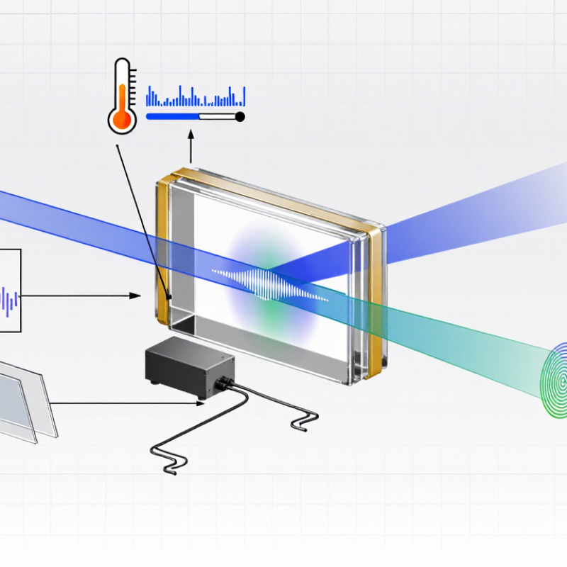
Table of Contents [Hide]
Definition and Purpose of a Polarization Modulator
A polarization modulator is an optical device that deliberately changes the polarization state of light. It may alter the angle of linear polarization, or convert light into an elliptical or circular state. Its purpose is to give researchers and engineers controlled access to these changes, rather than relying on fixed optical components.
In a common arrangement, linearly polarized light passes through an electro-optic crystal. A voltage changes the crystal’s optical properties, creating a phase delay between perpendicular components of the beam. The resulting polarization depends on the voltage, crystal orientation, and incoming light. The device does not always “rotate” light in the simple sense. That distinction matters. In a laboratory, an analyzer placed after the modulator can reveal the change as a shifting brightness pattern. Modulators support tasks such as optical measurement, imaging, and signal control. They can also help test how materials affect polarized light.
The label covers devices with different designs and operating limits. Speed, wavelength range, and temperature sensitivity can all affect performance. A setup that works cleanly on an optical bench may need careful alignment in a practical instrument. That detail is easy to underestimate. The basic definition is useful, but it does not capture every trade-off.

© Copyright - Pro Tool & Supply - Site by SVM E-Marketing Solutions - Sitemap
- Privacy policy