- Products
- Air Compressors & Air Tools
- Climate Control
- Compaction Equipment
- Concrete Cutting Tools & Equipment
- Concrete and Masonry
- Demolition & Excavation
- Electrical & Mechanical
- Fasteners and Anchoring Adhesives
- Floor Protection
- Generators and Welders
- Hand Tools
- Heaters
- Janitorial and Office Supplies
- Jobsite Protection
- Ladders & Storage
- Lighting & Lighting Accessories
- Man Lifts
- Material Handling Equipment
- Power Tools
- Pressure Washers & Pumps
- Safety Gear
- Safety Products
- Saws
- Surface Preparation
- SEASONAL PRODUCTS
- Rentals
- Air Compressor and Air Tool Rentals
- Climate Control Rental
- Compaction Rentals
- Concrete Equipment Rentals
- Demolition & Excavation Equipment Rentals
- Concrete Floor Grinder Rentals
- General Construction Equipment Rentals
- Generator Rentals and Welder Rentals
- Heater Rentals
- Light Tower Rentals
- Man Lift Rentals in Massachusetts and Rhode Island
- Material Handling Equipment Rentals
- Pressure Washer & Pump Rentals
- Saw Rentals in New England
- SEASONAL PRODUCTS
- Products
- Air Compressors & Air Tools
- Climate Control
- Compaction Equipment
- Concrete Cutting Tools & Equipment
- Demolition & Excavation
- Electrical & Mechanical
- Floor Protection
- Generators and Welders
- Construction Heaters
- Construction Ladders, Staging, & Storage
- Construction Lighting
- Man Lifts
- Material Handling Equipment
- Industrial Janitorial and Office Supplies
- Pressure Washers & Pumps
- Construction Safety Products
- Construction Safety Gear
- Surface Preparation
- Building Protection
- Diesel Accessories
- Zero Emissions
- Rentals
- Air Compressor and Air Tool Rentals
- Climate Control Rental
- Compaction Rentals
- Concrete Equipment Rental
- Demolition & Excavation Equipment Rental
- General Construction Equipment Rental
- Generator Rentals and Welder Rentals
- Construction Heaters Rental
- Light Tower Rentals
- Man Lift Rentals
- Material Handling Equipment Rental
- Pressure Washer & Pump Rentals
- Saw Rentals in New England
- Concrete Floor Grinder Rentals
- Zero Emissions Rentals
- Repairs & Used
- Parts
- Blog
- Services
- Resources
- About Us
- Contact Us
Sales & Rental of Construction | Industrial Equipment & Supplies


What Are Geothermal Wells and How Do They Work?
Geothermal Wells turn heat beneath our feet into usable energy, often through a carefully balanced underground circuit. A production well reaches hot rock, natural steam, or heated water. Pumps bring that fluid to the surface. A turbine, heat exchanger, or district-heating network then captures its energy. Cooler water returns through an injection well, helping maintain reservoir pressure.
The process sounds simple. It is not.
Well design depends on temperature, depth, rock permeability, chemistry, and local groundwater conditions. Engineers may drill several kilometers into the Earth, then install steel casing and cement to protect the wellbore. In shallow geothermal systems, closed-loop pipes circulate fluid underground without extracting groundwater. Deep systems may use naturally permeable reservoirs or carefully engineered fractures.
Industry data shows why this technology matters. The International Energy Agency’s 2024 report, The Future of Geothermal Energy, estimates geothermal could supply up to 15% of global electricity-demand growth by 2050. That pathway could represent almost 800 gigawatts of global capacity. The report also emphasizes drilling innovation, because well construction remains one of geothermal energy’s largest costs.
IRENA’s Renewable Capacity Statistics 2024 recorded roughly 15 gigawatts of installed geothermal power capacity worldwide. That figure is modest beside solar and wind. Yet geothermal plants can operate continuously, providing firm low-carbon power when weather conditions change.
There are uncertainties. Reservoir performance can decline, and drilling results are never guaranteed. Better exploration data may reduce those risks, but no report removes them entirely. Understanding Geothermal Wells requires examining both their impressive reliability and their demanding underground realities.
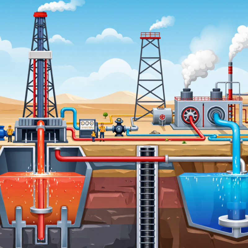
Table of Contents [Hide]
What Geothermal Wells Are: Boreholes Reaching 1–5 Kilometers Underground
Geothermal wells are deep boreholes drilled into the Earth, commonly reaching 1–5 kilometers underground. At these depths, surrounding rock can hold significant natural heat. Drilling crews create a narrow pathway through soil, sediment, and hard rock. Steel casing then supports the borehole and helps protect shallow groundwater from the circulating fluid.
A geothermal system usually uses two wells. The production well brings hot water or steam toward the surface. A second injection well returns cooler water underground. This repeated movement transfers heat from deep rock to a heat exchanger or power facility. In a heating system, the hot fluid may warm buildings directly. In a power system, it can create steam that turns a turbine.
Temperature, pressure, rock fractures, and water chemistry all affect performance. Field engineers measure these conditions during drilling and testing. Small changes in pressure can reveal blocked pathways or unwanted fluid movement. The process is technical, but the principle is simple. Heat rises through controlled circulation.
A deep well is not automatically a productive well. Some rock formations contain heat but allow little fluid flow. Others may cool faster than expected. This is where early forecasts can fail. Careful geological surveys, strong casing, and long-term monitoring remain essential. The underground system is powerful, but it is never perfectly predictable.

© Copyright - Pro Tool & Supply - Site by SVM E-Marketing Solutions - Sitemap
- Privacy policy