- Products
- Air Compressors & Air Tools
- Climate Control
- Compaction Equipment
- Concrete Cutting Tools & Equipment
- Concrete and Masonry
- Demolition & Excavation
- Electrical & Mechanical
- Fasteners and Anchoring Adhesives
- Floor Protection
- Generators and Welders
- Hand Tools
- Heaters
- Janitorial and Office Supplies
- Jobsite Protection
- Ladders & Storage
- Lighting & Lighting Accessories
- Man Lifts
- Material Handling Equipment
- Power Tools
- Pressure Washers & Pumps
- Safety Gear
- Safety Products
- Saws
- Surface Preparation
- SEASONAL PRODUCTS
- Rentals
- Air Compressor and Air Tool Rentals
- Climate Control Rental
- Compaction Rentals
- Concrete Equipment Rentals
- Demolition & Excavation Equipment Rentals
- Concrete Floor Grinder Rentals
- General Construction Equipment Rentals
- Generator Rentals and Welder Rentals
- Heater Rentals
- Light Tower Rentals
- Man Lift Rentals in Massachusetts and Rhode Island
- Material Handling Equipment Rentals
- Pressure Washer & Pump Rentals
- Saw Rentals in New England
- SEASONAL PRODUCTS
- Products
- Air Compressors & Air Tools
- Climate Control
- Compaction Equipment
- Concrete Cutting Tools & Equipment
- Demolition & Excavation
- Electrical & Mechanical
- Floor Protection
- Generators and Welders
- Construction Heaters
- Construction Ladders, Staging, & Storage
- Construction Lighting
- Man Lifts
- Material Handling Equipment
- Industrial Janitorial and Office Supplies
- Pressure Washers & Pumps
- Construction Safety Products
- Construction Safety Gear
- Surface Preparation
- Building Protection
- Diesel Accessories
- Zero Emissions
- Rentals
- Air Compressor and Air Tool Rentals
- Climate Control Rental
- Compaction Rentals
- Concrete Equipment Rental
- Demolition & Excavation Equipment Rental
- General Construction Equipment Rental
- Generator Rentals and Welder Rentals
- Construction Heaters Rental
- Light Tower Rentals
- Man Lift Rentals
- Material Handling Equipment Rental
- Pressure Washer & Pump Rentals
- Saw Rentals in New England
- Concrete Floor Grinder Rentals
- Zero Emissions Rentals
- Repairs & Used
- Parts
- Blog
- Services
- Resources
- About Us
- Contact Us
Sales & Rental of Construction | Industrial Equipment & Supplies


What Is a Fuse Holder and How Do You Choose One?
A Fuse Holder may look like a small plastic or ceramic fitting, but it carries a critical responsibility: keeping a fuse secure and making a reliable electrical connection. Choose the wrong one, and a fuse that fits physically may still be unsuitable for the circuit. Heat, vibration, moisture, and fault current all matter.
Industry standards offer a sound starting point. IEC 60269 specifies requirements for low-voltage fuses, while UL 4248 covers fuseholders. These standards help define performance and testing expectations; they do not replace checking the exact ratings of a particular product. A manufacturer’s datasheet should confirm fuse type, current and voltage ratings, mounting method, terminal style, and allowable operating temperature. Small details matter. A loose clip can generate heat.
Selection is practical, not mysterious. Picture a holder mounted inside a warm control cabinet, with wires pulling gently at its terminals. Check that the fuse fits securely, the terminals match the wiring, and the holder suits the enclosure and environment. Then verify that its ratings align with the circuit and the fuse manufacturer’s guidance. One caution: a holder’s rating alone does not prove that the complete assembly is suitable for every fault condition.
A named expert quotation should be verified against a reliable source before publication. No source material or verifiable expert statement was provided here, so attributing a quotation would risk inventing evidence. The sections ahead explain how to compare holder types, read specifications, and avoid common selection mistakes.
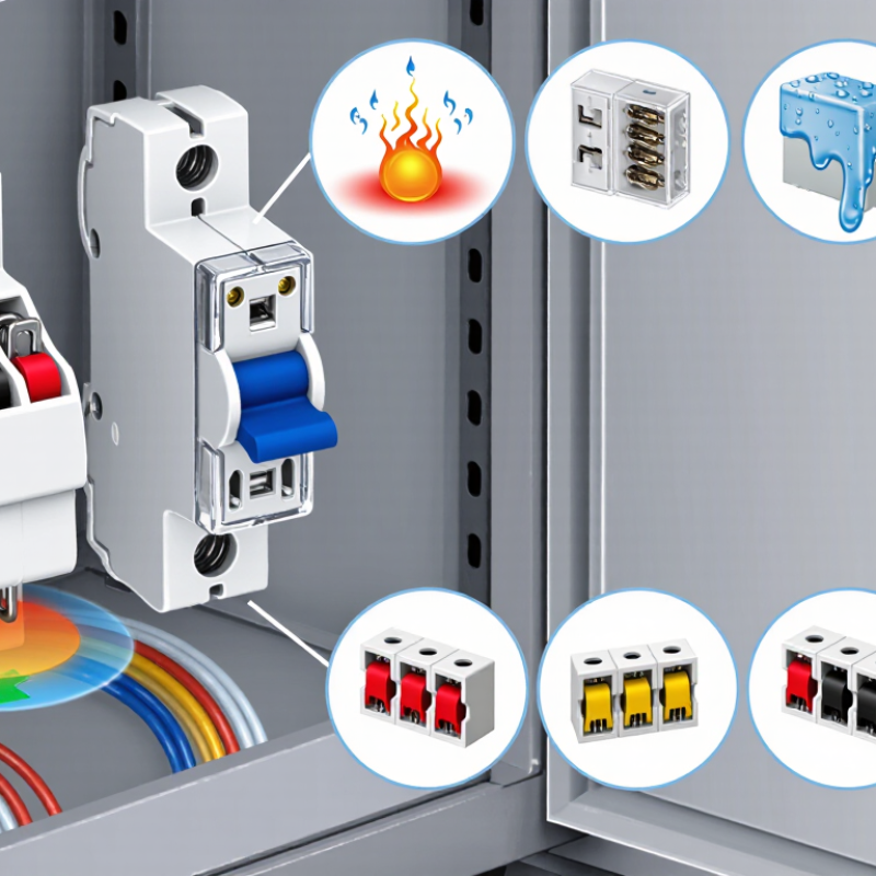
Table of Contents [Hide]
Fuse Holder: Definition, Purpose, and Basic Operation
A fuse holder is the insulated component that secures a fuse and connects it to an electrical circuit. It may use clips, a cap, or a cartridge-style enclosure. Its metal contacts keep the fuse in the current path, while its body helps prevent accidental contact with live parts. A holder does not interrupt excessive current by itself. The fuse inside does that work.
When current exceeds the fuse’s rated limit for long enough, a thin element inside the fuse heats and melts. This opens the circuit and stops current from reaching downstream equipment. The holder keeps the fuse aligned and maintains electrical contact during normal operation. A loose, corroded, or poorly matched holder can cause heat or unreliable connections. Small details matter.
Choose a holder that matches the fuse type, current and voltage ratings, and installation conditions. Check how it mounts and whether it can handle expected heat, vibration, and moisture. For example, a panel-mounted holder in a warm enclosure may need different ratings from one used in a dry indoor device. Turn off and verify power before replacing a fuse; if the correct rating is uncertain, consult the equipment documentation or a qualified technician. It can be easy to overlook the holder’s ratings. Don’t.

© Copyright - Pro Tool & Supply - Site by SVM E-Marketing Solutions - Sitemap
- Privacy policy