- Products
- Air Compressors & Air Tools
- Climate Control
- Compaction Equipment
- Concrete Cutting Tools & Equipment
- Concrete and Masonry
- Demolition & Excavation
- Electrical & Mechanical
- Fasteners and Anchoring Adhesives
- Floor Protection
- Generators and Welders
- Hand Tools
- Heaters
- Janitorial and Office Supplies
- Jobsite Protection
- Ladders & Storage
- Lighting & Lighting Accessories
- Man Lifts
- Material Handling Equipment
- Power Tools
- Pressure Washers & Pumps
- Safety Gear
- Safety Products
- Saws
- Surface Preparation
- SEASONAL PRODUCTS
- Rentals
- Air Compressor and Air Tool Rentals
- Climate Control Rental
- Compaction Rentals
- Concrete Equipment Rentals
- Demolition & Excavation Equipment Rentals
- Concrete Floor Grinder Rentals
- General Construction Equipment Rentals
- Generator Rentals and Welder Rentals
- Heater Rentals
- Light Tower Rentals
- Man Lift Rentals in Massachusetts and Rhode Island
- Material Handling Equipment Rentals
- Pressure Washer & Pump Rentals
- Saw Rentals in New England
- SEASONAL PRODUCTS
- Products
- Air Compressors & Air Tools
- Climate Control
- Compaction Equipment
- Concrete Cutting Tools & Equipment
- Demolition & Excavation
- Electrical & Mechanical
- Floor Protection
- Generators and Welders
- Construction Heaters
- Construction Ladders, Staging, & Storage
- Construction Lighting
- Man Lifts
- Material Handling Equipment
- Industrial Janitorial and Office Supplies
- Pressure Washers & Pumps
- Construction Safety Products
- Construction Safety Gear
- Surface Preparation
- Building Protection
- Diesel Accessories
- Zero Emissions
- Rentals
- Air Compressor and Air Tool Rentals
- Climate Control Rental
- Compaction Rentals
- Concrete Equipment Rental
- Demolition & Excavation Equipment Rental
- General Construction Equipment Rental
- Generator Rentals and Welder Rentals
- Construction Heaters Rental
- Light Tower Rentals
- Man Lift Rentals
- Material Handling Equipment Rental
- Pressure Washer & Pump Rentals
- Saw Rentals in New England
- Concrete Floor Grinder Rentals
- Zero Emissions Rentals
- Repairs & Used
- Parts
- Blog
- Services
- Resources
- About Us
- Contact Us
Sales & Rental of Construction | Industrial Equipment & Supplies

10 Tips for Buying Prefab Metal Buildings?
Prefab Metal Buildings are gaining attention because buyers want speed, predictable costs, and practical performance. Grand View Research valued the global prefabricated construction market at approximately $153.7 billion in 2022. Its report also projects strong growth through 2030. However, that market includes several building types, not only steel systems. Precision matters here.
The Metal Building Manufacturers Association has reported that metal building systems hold a significant share of low-rise, nonresidential construction in North America. Dodge Construction Network’s SmartMarket research also connects prefabrication with shorter schedules, better quality control, and reduced site waste. These advantages sound convincing. They are not automatic.
Tony Bouquot, former president and chief executive of the MBMA, describes the core idea clearly: “Metal building systems are an integrated design-and-manufacturing process.” That principle should guide every purchase decision. A supplier’s price is only one piece. Buyers must examine engineering responsibility, steel grades, insulation values, corrosion protection, delivery limits, and local installation experience. A low quote can hide expensive site preparation. A beautiful rendering can hide poor drainage.
This guide, “10 Tips for Buying Prefab Metal Buildings,” focuses on those practical details. It considers what happens after the contract is signed, when trucks arrive, anchors meet concrete, and weather interrupts installation. Some recommendations may seem obvious. They are still often missed. Buyers should question assumptions, verify every allowance, and compare complete building packages rather than isolated prices. No checklist removes all uncertainty. It can reduce avoidable surprises.
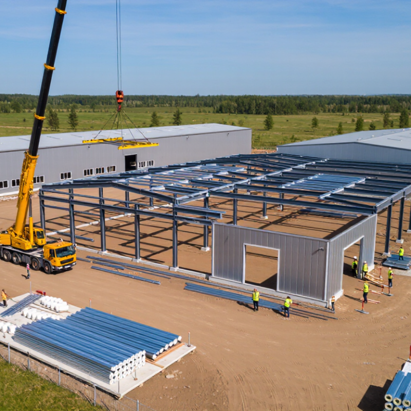
Table of Contents [Hide]
Define Building Use, Size, and Loads Under 2024 IBC and ASCE 7-22
10 Tips for Buying Prefab Metal Buildings?
Define Building Use, Size, and Loads Under 2024 IBC and ASCE 7-22
A prefab metal building starts with its intended use, not its exterior dimensions. Storage, retail, agriculture, and occupied offices create different code requirements. Under the 2024 International Building Code, occupancy affects risk category, fire protection, exits, and structural decisions. Describe equipment, storage racks, mezzanines, solar panels, and future expansions before requesting a price. A small omission can become an expensive redesign.
ASCE 7-22 requires site-specific evaluation of wind, snow, seismic, rain, flood, and other environmental loads. Wind design needs more than a city name. Exposure category, building height, enclosure classification, topography, and nearby obstructions matter. Snow drift near roof steps can control the design. Equipment loads can also change the roof framing. A neat spreadsheet can still hide a bad assumption.
NOAA recorded 28 U.S. billion-dollar weather and climate disasters in 2023, showing why generic load allowances deserve caution. FEMA’s Building Codes Save study estimates that modern codes could prevent more than 11 billion dollars in cumulative losses through 2060. Code compliance is not merely paperwork.
Ask for sealed calculations, geotechnical information, connection details, and a clear load path from roof to foundation. I would rather revise a quote than defend a weak assumption. Procurement schedules sometimes encourage shortcuts. That pressure needs resistance.
Sources: 2024 IBC, ASCE 7-22, NOAA National Centers for Environmental Information, and FEMA P-366.
© Copyright - Pro Tool & Supply - Site by SVM E-Marketing Solutions - Sitemap
- Privacy policy