- Products
- Air Compressors & Air Tools
- Climate Control
- Compaction Equipment
- Concrete Cutting Tools & Equipment
- Concrete and Masonry
- Demolition & Excavation
- Electrical & Mechanical
- Fasteners and Anchoring Adhesives
- Floor Protection
- Generators and Welders
- Hand Tools
- Heaters
- Janitorial and Office Supplies
- Jobsite Protection
- Ladders & Storage
- Lighting & Lighting Accessories
- Man Lifts
- Material Handling Equipment
- Power Tools
- Pressure Washers & Pumps
- Safety Gear
- Safety Products
- Saws
- Surface Preparation
- SEASONAL PRODUCTS
- Rentals
- Air Compressor and Air Tool Rentals
- Climate Control Rental
- Compaction Rentals
- Concrete Equipment Rentals
- Demolition & Excavation Equipment Rentals
- Concrete Floor Grinder Rentals
- General Construction Equipment Rentals
- Generator Rentals and Welder Rentals
- Heater Rentals
- Light Tower Rentals
- Man Lift Rentals in Massachusetts and Rhode Island
- Material Handling Equipment Rentals
- Pressure Washer & Pump Rentals
- Saw Rentals in New England
- SEASONAL PRODUCTS
- Products
- Air Compressors & Air Tools
- Climate Control
- Compaction Equipment
- Concrete Cutting Tools & Equipment
- Demolition & Excavation
- Electrical & Mechanical
- Floor Protection
- Generators and Welders
- Construction Heaters
- Construction Ladders, Staging, & Storage
- Construction Lighting
- Man Lifts
- Material Handling Equipment
- Industrial Janitorial and Office Supplies
- Pressure Washers & Pumps
- Construction Safety Products
- Construction Safety Gear
- Surface Preparation
- Building Protection
- Diesel Accessories
- Zero Emissions
- Rentals
- Air Compressor and Air Tool Rentals
- Climate Control Rental
- Compaction Rentals
- Concrete Equipment Rental
- Demolition & Excavation Equipment Rental
- General Construction Equipment Rental
- Generator Rentals and Welder Rentals
- Construction Heaters Rental
- Light Tower Rentals
- Man Lift Rentals
- Material Handling Equipment Rental
- Pressure Washer & Pump Rentals
- Saw Rentals in New England
- Concrete Floor Grinder Rentals
- Zero Emissions Rentals
- Repairs & Used
- Parts
- Blog
- Services
- Resources
- About Us
- Contact Us
Sales & Rental of Construction | Industrial Equipment & Supplies


What Is an Ebike Cable and Which Type Do You Need?
An Ebike Cable may look like a simple wire, yet it carries signals or power through the bicycle. Behind the frame, cables connect the battery, motor, controller, display, brake sensors, and other electrical parts. A loose connector can cause sudden cutouts, error codes, or a display that stays dark. The right replacement depends on the cable’s job, connector shape, pin layout, length, and system voltage. Small differences matter.
In practical inspections, I look for crushed insulation, bent pins, moisture marks, and strained cables near the handlebar. Motor cables are usually thicker and may include waterproof connectors. Display cables often carry communication signals, while brake-sensor cables can trigger motor cutoff. Battery and power cables require extra care because they handle higher current. Sensor cables may appear similar, but their wiring order can differ between systems. Matching the plug alone is not enough.
Manufacturers may use different names for similar cables. Some labels are unclear. That is where careful checking becomes more reliable than guessing. Record the bicycle’s brand, motor system, connector count, wire colors, and cable length before ordering. A service manual or authorized dealer can confirm compatibility when specifications conflict. I have found that even experienced owners can overlook one small pin. This guide explains the main Ebike Cable types, how they function, and which details deserve attention before installation. It will not replace professional service when wiring is damaged or battery connections are involved, but it can make the decision clearer and safer.
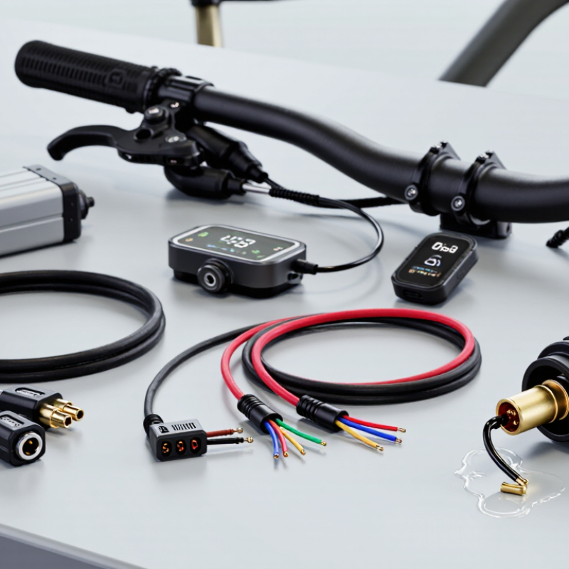
Table of Contents [Hide]
What an Ebike Cable Is and How It Connects the System
What Is an Ebike Cable and Which Type Do You Need?
An ebike cable carries power or signals between the battery, controller, motor, display, and sensors. It is more than a simple wire. Each cable uses specific conductors, connectors, and insulation for its job. Thick power cables handle battery current, while thinner signal cables carry speed or control data. Motor phase cables often contain three heavy wires. Smaller sensor cables may include five or six pins.
Cable selection depends on voltage, current, connector shape, pin layout, and cable length. A connector can fit physically but still use a different pin arrangement. That mistake may damage a controller or sensor. Check the wiring diagram before connecting anything. Inspect the plug for bent pins, loose seals, or moisture near the contacts. Outdoor riding exposes cables to rain, grit, and repeated movement.
Routing also affects reliability. Keep cables away from sharp frame edges and hot surfaces. Leave enough slack near the handlebar for full steering movement. I once saw a cable fail because it was pulled tight during a turn. The fault looked like a battery problem at first. Cable labels are useful, but they are not always accurate. Confirm each connection with a meter and the system’s technical documentation.
Disconnect the battery before checking or replacing wiring.

© Copyright - Pro Tool & Supply - Site by SVM E-Marketing Solutions - Sitemap
- Privacy policy