- Products
- Air Compressors & Air Tools
- Climate Control
- Compaction Equipment
- Concrete Cutting Tools & Equipment
- Concrete and Masonry
- Demolition & Excavation
- Electrical & Mechanical
- Fasteners and Anchoring Adhesives
- Floor Protection
- Generators and Welders
- Hand Tools
- Heaters
- Janitorial and Office Supplies
- Jobsite Protection
- Ladders & Storage
- Lighting & Lighting Accessories
- Man Lifts
- Material Handling Equipment
- Power Tools
- Pressure Washers & Pumps
- Safety Gear
- Safety Products
- Saws
- Surface Preparation
- SEASONAL PRODUCTS
- Rentals
- Air Compressor and Air Tool Rentals
- Climate Control Rental
- Compaction Rentals
- Concrete Equipment Rentals
- Demolition & Excavation Equipment Rentals
- Concrete Floor Grinder Rentals
- General Construction Equipment Rentals
- Generator Rentals and Welder Rentals
- Heater Rentals
- Light Tower Rentals
- Man Lift Rentals in Massachusetts and Rhode Island
- Material Handling Equipment Rentals
- Pressure Washer & Pump Rentals
- Saw Rentals in New England
- SEASONAL PRODUCTS
- Products
- Air Compressors & Air Tools
- Climate Control
- Compaction Equipment
- Concrete Cutting Tools & Equipment
- Demolition & Excavation
- Electrical & Mechanical
- Floor Protection
- Generators and Welders
- Construction Heaters
- Construction Ladders, Staging, & Storage
- Construction Lighting
- Man Lifts
- Material Handling Equipment
- Industrial Janitorial and Office Supplies
- Pressure Washers & Pumps
- Construction Safety Products
- Construction Safety Gear
- Surface Preparation
- Building Protection
- Diesel Accessories
- Zero Emissions
- Rentals
- Air Compressor and Air Tool Rentals
- Climate Control Rental
- Compaction Rentals
- Concrete Equipment Rental
- Demolition & Excavation Equipment Rental
- General Construction Equipment Rental
- Generator Rentals and Welder Rentals
- Construction Heaters Rental
- Light Tower Rentals
- Man Lift Rentals
- Material Handling Equipment Rental
- Pressure Washer & Pump Rentals
- Saw Rentals in New England
- Concrete Floor Grinder Rentals
- Zero Emissions Rentals
- Repairs & Used
- Parts
- Blog
- Services
- Resources
- About Us
- Contact Us
Sales & Rental of Construction | Industrial Equipment & Supplies


How to Choose the Right Wire Rope Thread Lifting Loop?
Choosing the correct Wire Rope Thread Lifting Loop is essential for safe, efficient, and repeatable lifting work. This component may look simple, yet its diameter, thread design, working load limit, and material quality directly affect performance. A loop used on a compact machinery frame may require different specifications from one supporting steel beams on a busy construction site.
Real-world selection begins with the load, lifting angle, connection point, and operating environment. Measure the available thread carefully. Check whether the loop matches the equipment’s thread size and strength rating. Then inspect the rope construction, protective finish, and manufacturer’s test documentation. Small details matter. A poorly matched thread can create uneven loading, while corrosion may weaken an apparently sound loop.
Experience also shows that labels alone are not enough. Confirm the working load limit under the actual lifting angle, not only the vertical rating. Consider repeated lifting, vibration, temperature changes, and possible edge contact. Competent suppliers should provide traceable certificates and clear inspection guidance. Independent verification is worthwhile when the load is valuable or the lifting arrangement is complex.
Some choices remain less obvious. A larger loop is not automatically safer, and a stronger rope cannot correct an unsuitable connection. I have seen selection decisions focus too heavily on price, then overlook inspection access and replacement intervals. That approach deserves reconsideration. A reliable choice combines technical data, practical handling, and documented maintenance. Before purchasing, compare the loop’s specifications with the equipment manual and consult a qualified lifting professional when uncertainty remains.
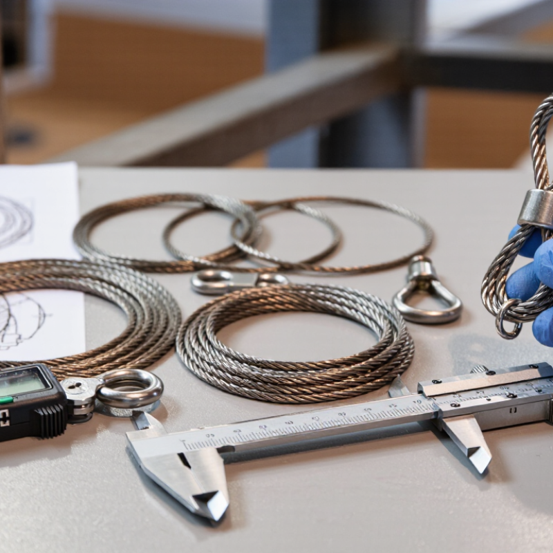
Table of Contents [Hide]
Understanding Wire Rope Thread Lifting Loop Design and Applications
How to Choose the Right Wire Rope Thread Lifting Loop?
A wire rope thread lifting loop is more than a cable bent into an eye. Its design includes rope diameter, core construction, eye length, ferrule type, thimble protection, and rated working load limit. A compact loop may fit a narrow lifting point, but poor curvature can crush the rope. Check the manufacturer’s load table, not appearance.
OSHA 1910.184 requires slings to show their rated capacity and receive regular inspections. That detail matters when loads swing, rotate, or lift at an angle.
Application changes the design. A thimble-supported eye suits repeated crane handling because it limits abrasion at the contact point. A soft eye may work for controlled, low-frequency lifting, but sharp hooks can flatten its crown. Keep the hook centered. Never force a loop onto a tip.
The angle between sling legs also increases tension; a 60-degree two-leg sling carries roughly 15% more tension than a vertical leg.
The U.S. Bureau of Labor Statistics recorded 1,069 fatal occupational injuries in transportation and material-moving occupations in 2023, showing why handling choices deserve careful review.
Inspect for broken wires, birdcaging, corrosion, heat marks, and slipped ferrules before each use. A clean loop can still be damaged inside.
I would also question “unused” stock stored near chemicals or moisture. Check it anyway.

© Copyright - Pro Tool & Supply - Site by SVM E-Marketing Solutions - Sitemap
- Privacy policy