- Products
- Air Compressors & Air Tools
- Climate Control
- Compaction Equipment
- Concrete Cutting Tools & Equipment
- Concrete and Masonry
- Demolition & Excavation
- Electrical & Mechanical
- Fasteners and Anchoring Adhesives
- Floor Protection
- Generators and Welders
- Hand Tools
- Heaters
- Janitorial and Office Supplies
- Jobsite Protection
- Ladders & Storage
- Lighting & Lighting Accessories
- Man Lifts
- Material Handling Equipment
- Power Tools
- Pressure Washers & Pumps
- Safety Gear
- Safety Products
- Saws
- Surface Preparation
- SEASONAL PRODUCTS
- Rentals
- Air Compressor and Air Tool Rentals
- Climate Control Rental
- Compaction Rentals
- Concrete Equipment Rentals
- Demolition & Excavation Equipment Rentals
- Concrete Floor Grinder Rentals
- General Construction Equipment Rentals
- Generator Rentals and Welder Rentals
- Heater Rentals
- Light Tower Rentals
- Man Lift Rentals in Massachusetts and Rhode Island
- Material Handling Equipment Rentals
- Pressure Washer & Pump Rentals
- Saw Rentals in New England
- SEASONAL PRODUCTS
- Products
- Air Compressors & Air Tools
- Climate Control
- Compaction Equipment
- Concrete Cutting Tools & Equipment
- Demolition & Excavation
- Electrical & Mechanical
- Floor Protection
- Generators and Welders
- Construction Heaters
- Construction Ladders, Staging, & Storage
- Construction Lighting
- Man Lifts
- Material Handling Equipment
- Industrial Janitorial and Office Supplies
- Pressure Washers & Pumps
- Construction Safety Products
- Construction Safety Gear
- Surface Preparation
- Building Protection
- Diesel Accessories
- Zero Emissions
- Rentals
- Air Compressor and Air Tool Rentals
- Climate Control Rental
- Compaction Rentals
- Concrete Equipment Rental
- Demolition & Excavation Equipment Rental
- General Construction Equipment Rental
- Generator Rentals and Welder Rentals
- Construction Heaters Rental
- Light Tower Rentals
- Man Lift Rentals
- Material Handling Equipment Rental
- Pressure Washer & Pump Rentals
- Saw Rentals in New England
- Concrete Floor Grinder Rentals
- Zero Emissions Rentals
- Repairs & Used
- Parts
- Blog
- Services
- Resources
- About Us
- Contact Us
Sales & Rental of Construction | Industrial Equipment & Supplies


7 Tips to Choose the Right Outdoor Isolator Switch?
Choosing the right Outdoor Isolator Switch is not a minor purchasing decision. It affects safety, maintenance, and the reliability of outdoor electrical equipment. A suitable switch should match the system’s voltage, current, enclosure rating, and installation environment.
Weather changes everything. Rain, dust, sunlight, salt air, and temperature changes can damage poorly selected equipment. During site inspections, electricians often notice problems caused by loose terminals, faded labels, or enclosures that cannot resist moisture. Small details matter. A switch may look strong in a catalogue but feel fragile during installation. That difference deserves attention.
This guide presents seven practical tips for making a more dependable choice. It considers load requirements, ingress protection, materials, switching capacity, visible isolation, mounting conditions, and routine maintenance. These points reflect common electrical practice and manufacturer guidance, but product documentation still needs careful checking. No single model suits every property. A coastal home, a workshop, and a rooftop air-conditioning unit face different risks.
Reliable selection also requires honest judgement. A higher price does not automatically mean better protection. An attractive enclosure cannot compensate for incorrect ratings or poor cable entry. Installation should be completed by a qualified professional who can verify compatibility and local requirements. The goal is simple: choose an Outdoor Isolator Switch that remains secure, accessible, and dependable when the weather turns difficult.
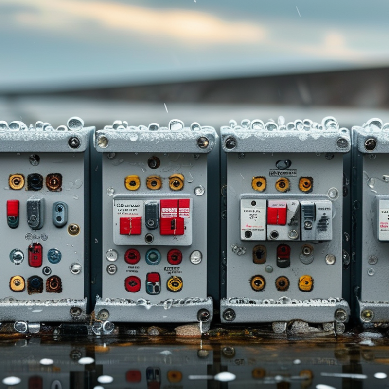
Table of Contents [Hide]
Define the Load: Voltage, Current, Poles, and AC-23A Utilization Category
Choosing an outdoor isolator switch starts with the load, not the enclosure. Record the system voltage, operating current, phases, poles, and load type. The IEC 60947-3 standard separates utilization categories because switching a heater differs from switching a motor. AC-23A is intended for motors and other highly inductive loads, where starting current can sharply exceed the nameplate value.
Check the rating at the actual voltage and frequency. A 32 A marking alone is incomplete. A motor may draw 18 A during operation but create a much higher inrush current. The isolator must withstand and switch that duty under AC-23A conditions. It must also isolate every required live conductor. For three-phase equipment, this usually means three poles; systems with a switched neutral may require four.
Outdoor installations deserve practical scrutiny. Rising electrical demand is increasing the number of external pumps, compressors, and charging systems; the International Energy Agency’s Electricity 2024 report projected global electricity demand growth of about 4% in 2024 and 2025. Select an enclosure suitable for rain, dust, sunlight, and temperature changes, but do not confuse ingress protection with load capacity. Overcurrent protection remains a separate requirement. I have seen selections based only on continuous current. That shortcut is easy to make, and sometimes wrong. Recheck the motor data, cable arrangement, switching frequency, and fault conditions before final selection.
7 Tips to Choose the Right Outdoor Isolator Switch? - Define the Load: Voltage, Current, Poles, and AC-23A Utilization Category
| Tip | Selection Dimension | Typical Data or Requirement | Example Application | What to Verify |
|---|---|---|---|---|
| 1 | Define the rated voltage | Select a switch with a rated operational voltage (Ue) equal to or higher than the system voltage. Common low-voltage systems include 230 V single-phase and 400 V three-phase AC. | 400 V AC, three-phase motor circuit | Confirm the supply voltage, frequency, insulation voltage, and applicable electrical standard. |
| 2 | Calculate the load current | The switch current rating should not be lower than the design current. For a three-phase motor, approximate current can be estimated using: I = P ÷ (√3 × V × η × cos φ). | 11 kW motor at 400 V, efficiency 0.90, power factor 0.85: approximately 20.8 A | Use the equipment nameplate current and consider ambient temperature, enclosure grouping, cable capacity, and motor starting conditions. |
| 3 | Choose the correct number of poles | Use 2 poles for single-phase line and neutral isolation where required, 3 poles for three-phase line isolation, and 4 poles when the neutral must also be switched. | 3-pole isolator for a 400 V three-phase motor; 4-pole isolator for three-phase equipment requiring neutral disconnection | Check the wiring system, earthing arrangement, neutral-switching requirements, and local regulations. The protective earth conductor must not be switched. |
| 4 | Match the AC-23A utilization category | AC-23A is intended for switching motor loads and other highly inductive loads. It is more demanding than AC-21A, which is mainly associated with resistive loads. | Direct switching or isolation of a motor, compressor, pump, or fan circuit | Read the manufacturer’s AC-23A rating at the actual operating voltage and verify whether the switch is intended for switching or only for isolation. |
| 5 | Allow for starting and switching duty | Motor starting current can be several times the normal running current. A suitable switch must have adequate utilization-category performance and making and breaking capability. | A motor with a 21 A running current may draw a substantially higher inrush current during direct-on-line starting. | Check motor starting method, switching frequency, operational current, short-circuit protection, and the switch’s rated making and breaking capacity. |
| 6 | Select the outdoor protection level | Choose an enclosure with an ingress protection rating suitable for exposure. IP65 provides dust-tight protection and protection against water jets; IP66 provides protection against powerful water jets. | IP65 or IP66 enclosure for an outdoor pump or air-conditioning isolator, subject to installation conditions | Verify UV resistance, corrosion resistance, temperature range, cable-gland sealing, condensation control, and protection against impact where relevant. |
| 7 | Confirm isolation and installation requirements | The isolator should provide a clear OFF position, reliable mechanical isolation, suitable terminal capacity, and a lockable handle where maintenance safety requires it. | Lockable local isolator mounted within sight and reach of outdoor motor-driven equipment | Check clearance and creepage distances, conductor size range, tightening torque, mounting orientation, accessibility, labeling, and compliance with the installation code. |
Reference note: AC-23A and AC-21A are utilization categories used for low-voltage switch-disconnectors and switches. The final selection must be based on the complete equipment rating, installation conditions, protection system, and applicable local electrical requirements.

© Copyright - Pro Tool & Supply - Site by SVM E-Marketing Solutions - Sitemap
- Privacy policy