- Products
- Air Compressors & Air Tools
- Climate Control
- Compaction Equipment
- Concrete Cutting Tools & Equipment
- Concrete and Masonry
- Demolition & Excavation
- Electrical & Mechanical
- Fasteners and Anchoring Adhesives
- Floor Protection
- Generators and Welders
- Hand Tools
- Heaters
- Janitorial and Office Supplies
- Jobsite Protection
- Ladders & Storage
- Lighting & Lighting Accessories
- Man Lifts
- Material Handling Equipment
- Power Tools
- Pressure Washers & Pumps
- Safety Gear
- Safety Products
- Saws
- Surface Preparation
- SEASONAL PRODUCTS
- Rentals
- Air Compressor and Air Tool Rentals
- Climate Control Rental
- Compaction Rentals
- Concrete Equipment Rentals
- Demolition & Excavation Equipment Rentals
- Concrete Floor Grinder Rentals
- General Construction Equipment Rentals
- Generator Rentals and Welder Rentals
- Heater Rentals
- Light Tower Rentals
- Man Lift Rentals in Massachusetts and Rhode Island
- Material Handling Equipment Rentals
- Pressure Washer & Pump Rentals
- Saw Rentals in New England
- SEASONAL PRODUCTS
- Products
- Air Compressors & Air Tools
- Climate Control
- Compaction Equipment
- Concrete Cutting Tools & Equipment
- Demolition & Excavation
- Electrical & Mechanical
- Floor Protection
- Generators and Welders
- Construction Heaters
- Construction Ladders, Staging, & Storage
- Construction Lighting
- Man Lifts
- Material Handling Equipment
- Industrial Janitorial and Office Supplies
- Pressure Washers & Pumps
- Construction Safety Products
- Construction Safety Gear
- Surface Preparation
- Building Protection
- Diesel Accessories
- Zero Emissions
- Rentals
- Air Compressor and Air Tool Rentals
- Climate Control Rental
- Compaction Rentals
- Concrete Equipment Rental
- Demolition & Excavation Equipment Rental
- General Construction Equipment Rental
- Generator Rentals and Welder Rentals
- Construction Heaters Rental
- Light Tower Rentals
- Man Lift Rentals
- Material Handling Equipment Rental
- Pressure Washer & Pump Rentals
- Saw Rentals in New England
- Concrete Floor Grinder Rentals
- Zero Emissions Rentals
- Repairs & Used
- Parts
- Blog
- Services
- Resources
- About Us
- Contact Us
Sales & Rental of Construction | Industrial Equipment & Supplies


How to Choose the Right Iron Ball Valve?
Choosing an Iron Ball Valve is not simply a matter of matching the pipe size. The right selection depends on the fluid, operating pressure, temperature range, flow requirements, and installation environment. An iron body may suit many water and general-service systems, but the word “iron” alone does not confirm that a valve is suitable. Body grade, ball and stem materials, seat composition, and end connections all affect performance. Small details matter. A valve exposed to grit, chemical additives, outdoor moisture, or frequent operation may need different materials and maintenance. A mismatch can lead to leakage, difficult operation, or premature wear.
This guide outlines practical checks for comparing valve options. Start with the manufacturer’s pressure and temperature ratings, then confirm that the wetted materials are compatible with the actual fluid. Check whether the port design provides the flow capacity your system needs, and whether the connection type fits the existing line. Manual and actuated models also have different space and control requirements. Ball valves are commonly used for shutoff; do not assume every model is suited to throttling. That distinction is easy to overlook. A specification sheet can appear complete while leaving out real operating conditions, such as temperature swings or occasional solids. Verify those details with reliable product documentation or a qualified supplier before purchase. The best choice is the one that matches the service conditions, not merely the lowest price or a familiar label.
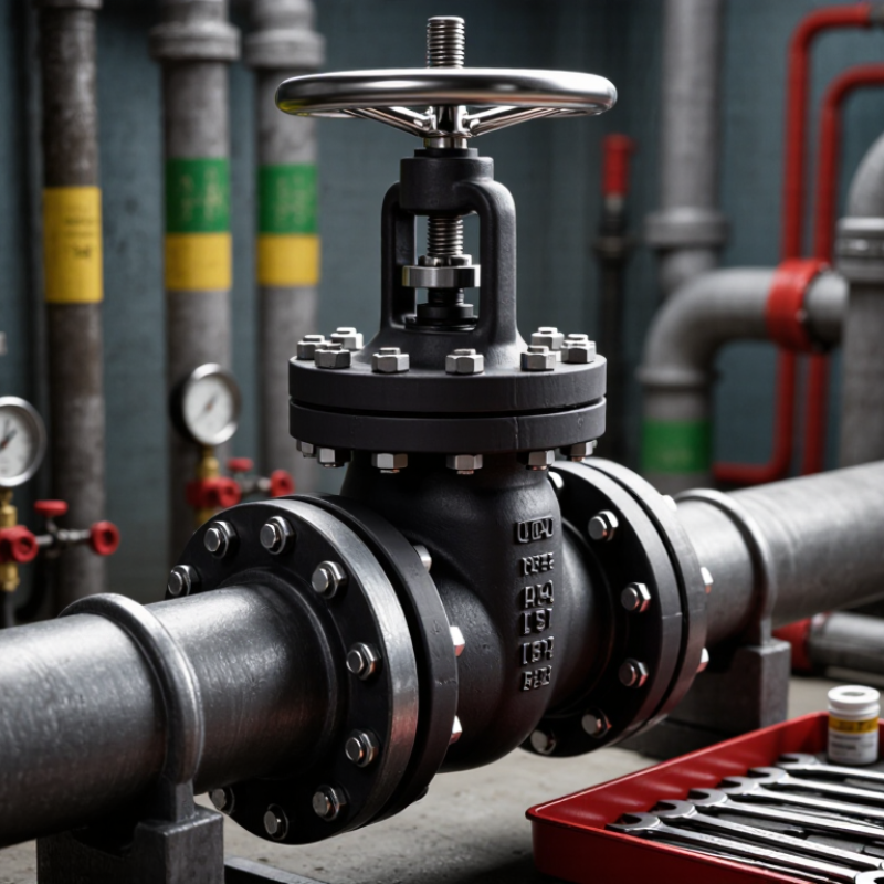
Table of Contents [Hide]
Understanding Iron Ball Valves and How They Work
An iron ball valve usually has a cast-iron body, a spherical closure, and seats that seal around the ball. Turn the handle one quarter-turn, and the ball’s bore aligns with the pipe; turn it again, and the flow stops. Simple motion. The actual assembly may be less simple: the ball and seats can use different materials, so “iron” does not describe every wetted part.
For pressure-containing castings, ASTM A126 Class B specifies a minimum tensile strength of 31,000 psi for gray iron. That figure describes material strength, not the valve’s permitted working pressure. It is an easy distinction to miss. Check the valve’s pressure-temperature rating, connection type, and fluid compatibility instead of choosing by body material alone. In a plant room, also consider how often the valve will cycle and whether grit could score its seats. I would verify those details against the service conditions; a familiar-looking handle is not proof that the valve fits the job.

© Copyright - Pro Tool & Supply - Site by SVM E-Marketing Solutions - Sitemap
- Privacy policy