- Products
- Air Compressors & Air Tools
- Climate Control
- Compaction Equipment
- Concrete Cutting Tools & Equipment
- Concrete and Masonry
- Demolition & Excavation
- Electrical & Mechanical
- Fasteners and Anchoring Adhesives
- Floor Protection
- Generators and Welders
- Hand Tools
- Heaters
- Janitorial and Office Supplies
- Jobsite Protection
- Ladders & Storage
- Lighting & Lighting Accessories
- Man Lifts
- Material Handling Equipment
- Power Tools
- Pressure Washers & Pumps
- Safety Gear
- Safety Products
- Saws
- Surface Preparation
- SEASONAL PRODUCTS
- Rentals
- Air Compressor and Air Tool Rentals
- Climate Control Rental
- Compaction Rentals
- Concrete Equipment Rentals
- Demolition & Excavation Equipment Rentals
- Concrete Floor Grinder Rentals
- General Construction Equipment Rentals
- Generator Rentals and Welder Rentals
- Heater Rentals
- Light Tower Rentals
- Man Lift Rentals in Massachusetts and Rhode Island
- Material Handling Equipment Rentals
- Pressure Washer & Pump Rentals
- Saw Rentals in New England
- SEASONAL PRODUCTS
- Products
- Air Compressors & Air Tools
- Climate Control
- Compaction Equipment
- Concrete Cutting Tools & Equipment
- Demolition & Excavation
- Electrical & Mechanical
- Floor Protection
- Generators and Welders
- Construction Heaters
- Construction Ladders, Staging, & Storage
- Construction Lighting
- Man Lifts
- Material Handling Equipment
- Industrial Janitorial and Office Supplies
- Pressure Washers & Pumps
- Construction Safety Products
- Construction Safety Gear
- Surface Preparation
- Building Protection
- Diesel Accessories
- Zero Emissions
- Rentals
- Air Compressor and Air Tool Rentals
- Climate Control Rental
- Compaction Rentals
- Concrete Equipment Rental
- Demolition & Excavation Equipment Rental
- General Construction Equipment Rental
- Generator Rentals and Welder Rentals
- Construction Heaters Rental
- Light Tower Rentals
- Man Lift Rentals
- Material Handling Equipment Rental
- Pressure Washer & Pump Rentals
- Saw Rentals in New England
- Concrete Floor Grinder Rentals
- Zero Emissions Rentals
- Repairs & Used
- Parts
- Blog
- Services
- Resources
- About Us
- Contact Us
Sales & Rental of Construction | Industrial Equipment & Supplies


How to Choose Geosynthetic Materials in 2026?
Choosing Geo Synthetic Materials in 2026 requires more than comparing product prices or tensile strength. Engineers must connect each material with the project’s actual risks, climate, soil behavior, and construction conditions. A drainage geocomposite beside a highway cannot be judged like a geomembrane beneath a landfill. The details matter.
Dr. Robert M. Koerner, a leading geosynthetics authority, stated, “The proper selection of a geosynthetic requires an understanding of its function, the site conditions, and the installation environment.” This principle remains highly relevant in 2026. Material selection should examine filtration, separation, reinforcement, drainage, containment, puncture resistance, chemical compatibility, and long-term durability. Laboratory data helps. It does not replace field judgment.
Look closely at the site.
A wet clay embankment may need reinforcement with controlled interface friction. A reservoir liner may require welding performance, ultraviolet resistance, and verified leak testing. A temporary construction road may prioritize survivability under repeated vehicle loads. These examples show why one “strongest” product rarely exists.
Reliable decisions also depend on documented testing, qualified installers, traceable manufacturing, and independent technical review. Environmental conditions are changing, yet some specifications still depend on outdated assumptions. That weakness deserves attention.
This guide examines practical selection methods for 2026, including performance testing, life-cycle value, installation quality, and project-specific risk. It also recognizes an uncomfortable truth: even excellent Geo Synthetic Materials can fail when design communication is poor or site conditions are underestimated. The best choice is not always the most advanced material. It is the material whose performance can be justified, inspected, and maintained throughout the project’s intended life.
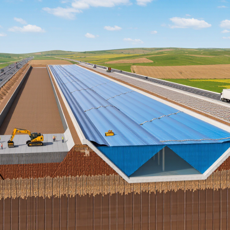
Table of Contents [Hide]
What Are Geosynthetic Materials and Where Are They Used?
Geosynthetic materials are engineered polymer products used with soil, rock, or other construction materials. They include geotextiles, geomembranes, geogrids, geonets, and geocomposites. Each type performs a different function. Some separate unstable soil layers. Others filter water, reinforce slopes, control erosion, or prevent leakage.
Their uses are practical and widespread. On roads, geotextiles can separate clay from aggregate and reduce rutting after heavy rain. Geogrids reinforce weak foundations beneath roads, railway tracks, and parking areas. Geomembranes create low-permeability barriers in reservoirs, wastewater ponds, and engineered waste containment systems. Geocomposites can collect and drain water behind retaining walls or beneath landfills. I have seen drainage failures caused by blocked outlets, not poor product strength. Small details matter.
Choosing materials in 2026 requires more than comparing tensile strength. Engineers should examine soil chemistry, ultraviolet exposure, installation damage, temperature changes, and expected water pressure. Recycled content may support sustainability goals, but it must not compromise durability or quality control. Laboratory data helps, yet field conditions can differ sharply. A sample may pass testing and still fail after careless placement. That risk deserves attention. Site inspection, certified testing, and clear installation records improve reliability. Forecasts for heavier rainfall also make drainage capacity increasingly important, although local climate assumptions can still be wrong.

© Copyright - Pro Tool & Supply - Site by SVM E-Marketing Solutions - Sitemap
- Privacy policy