- Products
- Air Compressors & Air Tools
- Climate Control
- Compaction Equipment
- Concrete Cutting Tools & Equipment
- Concrete and Masonry
- Demolition & Excavation
- Electrical & Mechanical
- Fasteners and Anchoring Adhesives
- Floor Protection
- Generators and Welders
- Hand Tools
- Heaters
- Janitorial and Office Supplies
- Jobsite Protection
- Ladders & Storage
- Lighting & Lighting Accessories
- Man Lifts
- Material Handling Equipment
- Power Tools
- Pressure Washers & Pumps
- Safety Gear
- Safety Products
- Saws
- Surface Preparation
- SEASONAL PRODUCTS
- Rentals
- Air Compressor and Air Tool Rentals
- Climate Control Rental
- Compaction Rentals
- Concrete Equipment Rentals
- Demolition & Excavation Equipment Rentals
- Concrete Floor Grinder Rentals
- General Construction Equipment Rentals
- Generator Rentals and Welder Rentals
- Heater Rentals
- Light Tower Rentals
- Man Lift Rentals in Massachusetts and Rhode Island
- Material Handling Equipment Rentals
- Pressure Washer & Pump Rentals
- Saw Rentals in New England
- SEASONAL PRODUCTS
- Products
- Air Compressors & Air Tools
- Climate Control
- Compaction Equipment
- Concrete Cutting Tools & Equipment
- Demolition & Excavation
- Electrical & Mechanical
- Floor Protection
- Generators and Welders
- Construction Heaters
- Construction Ladders, Staging, & Storage
- Construction Lighting
- Man Lifts
- Material Handling Equipment
- Industrial Janitorial and Office Supplies
- Pressure Washers & Pumps
- Construction Safety Products
- Construction Safety Gear
- Surface Preparation
- Building Protection
- Diesel Accessories
- Zero Emissions
- Rentals
- Air Compressor and Air Tool Rentals
- Climate Control Rental
- Compaction Rentals
- Concrete Equipment Rental
- Demolition & Excavation Equipment Rental
- General Construction Equipment Rental
- Generator Rentals and Welder Rentals
- Construction Heaters Rental
- Light Tower Rentals
- Man Lift Rentals
- Material Handling Equipment Rental
- Pressure Washer & Pump Rentals
- Saw Rentals in New England
- Concrete Floor Grinder Rentals
- Zero Emissions Rentals
- Repairs & Used
- Parts
- Blog
- Services
- Resources
- About Us
- Contact Us
Sales & Rental of Construction | Industrial Equipment & Supplies


How to Choose the Right Cutout Electric Fuse?
Choosing the right Cutout Electric Fuse is a practical protection decision, not a simple catalog search. The fuse must match the system voltage, continuous load, fault current, installation environment, and equipment requirements. A rural transformer, for example, may face lightning, moisture, and repeated temporary faults. An indoor feeder may demand different performance.
Dr. John D. McDonald, a recognized power-system protection engineer, emphasizes, “Protection should be coordinated with the equipment it serves, not selected in isolation.” This principle guides the selection process. A fuse that opens too quickly can interrupt normal energizing current. One that opens too slowly may leave a transformer exposed to damaging fault energy. Both choices can look acceptable on paper.
Field experience adds another layer. Technicians inspect conductor size, mounting condition, ambient temperature, and the available fault current. They also compare the fuse time-current curve with upstream and downstream devices. Small details matter. A loose contact can create heat. A contaminated insulator can reduce reliability.
The process is not perfectly tidy. Manufacturer data may use different test conditions. Existing drawings may be incomplete. A calculated fault level may not reflect future network changes. That uncertainty deserves attention.
This guide explains how to compare ratings, interrupting capacity, fuse links, coordination, and installation requirements. It also highlights common selection mistakes. The goal is dependable protection, clearer maintenance decisions, and safer electrical operation. In practice, careful verification remains essential. No single rating tells the whole story.
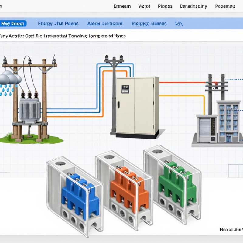
Table of Contents [Hide]
What Is a Cutout Electric Fuse and How Does It Work?
A cutout electric fuse is a protective device used on overhead power systems. It combines a fuse link with a hinged carrier and an insulating body. Under normal conditions, current passes through the link without interruption. When a short circuit or overload occurs, the link heats rapidly and melts. The circuit then opens, limiting damage to conductors and equipment. The carrier may drop visibly after operation. This creates a clear isolation point for trained workers. Simple, but not crude.
Choosing the correct fuse requires more than matching physical size. Check the system voltage and continuous current rating first. The fuse must also have enough interrupting capacity for the available fault current. Its time-current characteristic should coordinate with upstream and downstream protection. A mismatch can cause unnecessary outages or delayed fault clearing. Outdoor conditions matter too. Moisture, dust, sunlight, and salt exposure can affect insulation and mechanical performance. Always verify the installation requirements and approved technical documentation.
Field inspections often reveal a basic mistake: the fuse rating was selected from normal load alone. Starting currents and future load changes were ignored. That approach can create nuisance operations or unsafe overheating. Examine contact pressure, hinge movement, corrosion, and signs of arcing. Replace damaged parts with the specified type, not a convenient substitute. Do not rely on appearance alone. A fuse can look intact while its connection is already unreliable. Qualified personnel should test and install the device under applicable electrical safety procedures.
How to Choose the Right Cutout Electric Fuse? - What Is a Cutout Electric Fuse and How Does It Work?
| Selection Dimension | What to Check | Typical Distribution-Fuse Data | Why It Matters |
|---|---|---|---|
| Device Type | Expulsion cutout fuse | An outdoor medium-voltage protective device that combines a fuse holder, fuse link, and an insulating cutout body. | The fuse link melts during an overcurrent. The fuse holder then drops open, providing visible isolation and helping interrupt the fault. |
| System Voltage | Select a voltage rating equal to or higher than the maximum system voltage. | Common distribution classes include 7.2 kV, 15 kV, 27 kV, and 38 kV equipment classes, depending on the network. | The cutout must withstand normal operating voltage, temporary overvoltage, and the system's insulation requirements. |
| System Frequency | Match the operating frequency of the electrical network. | Utility distribution networks commonly operate at 50 Hz or 60 Hz. | The fuse and cutout assembly must be tested and rated for the network frequency to ensure correct dielectric and interrupting performance. |
| Continuous Current | Choose a cutout current rating above the highest expected continuous load current. | Common cutout frame ratings include 100 A and 200 A. Higher ratings may be available for specific applications. | The rating must accommodate normal load, permissible overload, transformer inrush, and expected future load growth without overheating. |
| Fuse-Link Ampere Rating | Coordinate the fuse-link rating with the protected transformer, feeder, or lateral. | Fuse links are available in many ratings, often from a few amperes to approximately 200 A, depending on the fuse-link type and cutout. | A fuse link that is too small may operate during normal energization; one that is too large may not protect equipment against damaging overcurrent. |
| Time-Current Characteristic | Select the required speed and characteristic, such as fast or time-delay operation. | Fast links generally clear lower-duration faults quickly, while time-delay links better tolerate transformer magnetizing inrush and short-duration overloads. | Time-current coordination helps the nearest protective device operate first and reduces unnecessary interruptions to upstream circuits. |
| Interrupting Rating | Verify that the interrupting capability exceeds the available fault current at the installation point. | Medium-voltage cutout interrupting ratings vary by design; values such as 6.3 kA, 8 kA, and 10 kA are used in distribution applications. | The device must safely interrupt the maximum prospective fault current, not merely the normal operating current. |
| Insulation and BIL | Check basic insulation level, dry power-frequency withstand, and wet withstand requirements. | Common distribution equipment BIL values include 95 kV for many 15 kV-class applications and 125 kV for many 25–28 kV-class applications. | Adequate insulation withstand reduces the risk of flashover caused by lightning, switching surges, or wet outdoor conditions. |
| Transformer Protection | Compare the fuse-link characteristic with transformer full-load current and magnetizing inrush. | The fuse link should carry normal transformer load and inrush while still providing protection against internal transformer faults and severe secondary faults. | Coordination prevents nuisance operations during energization and supports selective protection of the transformer and upstream equipment. |
| Mounting and Environment | Confirm pole, crossarm, bracket, clearance, altitude, pollution, and weather conditions. | Cutouts are normally designed for outdoor exposure, but installation conditions may require additional creepage distance or derating. | Environmental factors can affect insulation strength, heating, mechanical operation, and long-term reliability. |
| Operation and Indication | Determine whether visible fuse operation, manual loadbreak capability, or remote indication is required. | Standard cutouts provide visible open-circuit indication after fuse operation. Loadbreak versions include features for approved manual load interruption. | Visible isolation improves maintenance safety, while loadbreak capability must not be assumed unless the device is specifically rated and approved for that duty. |
| Applicable Standards | Use equipment tested to the standard required by the local utility, authority, or project specification. | IEEE C37.41 and IEEE C37.42 are widely referenced for distribution cutouts and fuse links in North American practice. IEC requirements may apply in other regions. | Standards define construction, rating, testing, dielectric performance, and interrupting requirements for reliable application. |
| Final Selection Rule | Confirm voltage, frequency, continuous current, fuse-link rating, time-current curve, interrupting rating, insulation level, and environmental suitability. | The correct choice is the smallest properly coordinated fuse link that carries expected load and inrush while remaining within the cutout and system ratings. | Always verify the final selection against the available fault-current study, transformer data, protection-coordination study, and local electrical requirements. |
Important: Actual ratings and fuse-link characteristics vary by construction, standard, voltage class, and application. Final selection should be checked against the system short-circuit current, transformer inrush data, coordination curves, installation conditions, and applicable electrical codes.

© Copyright - Pro Tool & Supply - Site by SVM E-Marketing Solutions - Sitemap
- Privacy policy