- Products
- Air Compressors & Air Tools
- Climate Control
- Compaction Equipment
- Concrete Cutting Tools & Equipment
- Concrete and Masonry
- Demolition & Excavation
- Electrical & Mechanical
- Fasteners and Anchoring Adhesives
- Floor Protection
- Generators and Welders
- Hand Tools
- Heaters
- Janitorial and Office Supplies
- Jobsite Protection
- Ladders & Storage
- Lighting & Lighting Accessories
- Man Lifts
- Material Handling Equipment
- Power Tools
- Pressure Washers & Pumps
- Safety Gear
- Safety Products
- Saws
- Surface Preparation
- SEASONAL PRODUCTS
- Rentals
- Air Compressor and Air Tool Rentals
- Climate Control Rental
- Compaction Rentals
- Concrete Equipment Rentals
- Demolition & Excavation Equipment Rentals
- Concrete Floor Grinder Rentals
- General Construction Equipment Rentals
- Generator Rentals and Welder Rentals
- Heater Rentals
- Light Tower Rentals
- Man Lift Rentals in Massachusetts and Rhode Island
- Material Handling Equipment Rentals
- Pressure Washer & Pump Rentals
- Saw Rentals in New England
- SEASONAL PRODUCTS
- Products
- Air Compressors & Air Tools
- Climate Control
- Compaction Equipment
- Concrete Cutting Tools & Equipment
- Demolition & Excavation
- Electrical & Mechanical
- Floor Protection
- Generators and Welders
- Construction Heaters
- Construction Ladders, Staging, & Storage
- Construction Lighting
- Man Lifts
- Material Handling Equipment
- Industrial Janitorial and Office Supplies
- Pressure Washers & Pumps
- Construction Safety Products
- Construction Safety Gear
- Surface Preparation
- Building Protection
- Diesel Accessories
- Zero Emissions
- Rentals
- Air Compressor and Air Tool Rentals
- Climate Control Rental
- Compaction Rentals
- Concrete Equipment Rental
- Demolition & Excavation Equipment Rental
- General Construction Equipment Rental
- Generator Rentals and Welder Rentals
- Construction Heaters Rental
- Light Tower Rentals
- Man Lift Rentals
- Material Handling Equipment Rental
- Pressure Washer & Pump Rentals
- Saw Rentals in New England
- Concrete Floor Grinder Rentals
- Zero Emissions Rentals
- Repairs & Used
- Parts
- Blog
- Services
- Resources
- About Us
- Contact Us
Sales & Rental of Construction | Industrial Equipment & Supplies


How to Choose the Right Bus Bar Copper in 2026?
In 2026, choosing the right Bus Bar Copper means matching material, dimensions, and operating conditions—not simply buying the highest-conductivity grade. A busbar carrying steady current in a clean indoor cabinet faces different demands from one exposed to heat, vibration, or moisture. Small details matter: a narrow contact area, a rough cut edge, or a loose joint can create unwanted resistance and heat. Looks are not enough.
Start by checking the copper grade, conductivity data, temper, and relevant test documentation against your project specification. Then consider current load, allowable temperature rise, enclosure ventilation, and the space available for bends and connections. Ask suppliers for traceable material records and clear dimensional tolerances. Where connections are critical, confirm that the chosen surface finish and joining method are compatible with the rest of the assembly. A datasheet helps, but it cannot replace sound design calculations or qualified review.
There is no universal “best” copper busbar. Cost, formability, electrical performance, and service conditions can pull in different directions. A grade that works well in one cabinet may be a poor fit in another. That is easy to overlook when comparing prices alone. Before ordering, review the actual installation, verify assumptions with the equipment designer, and document why the selection fits. Even careful choices deserve a second look when loads, ambient temperatures, or layouts change.
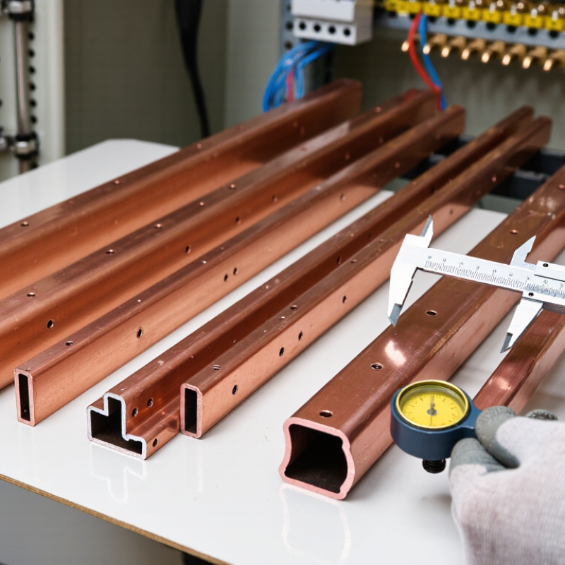
Table of Contents [Hide]
Define the Electrical and Mechanical Requirements of the Bus Bar
How to Choose the Right Bus Bar Copper in 2026?
Define the Electrical and Mechanical Requirements of the Bus Bar
A copper bus bar should be selected for its actual operating conditions, not just its nominal current rating. Define continuous current, peak current, voltage, and expected fault conditions. Record the permitted voltage drop and temperature rise, too. These figures affect conductor dimensions and cooling needs. Small details matter. A bar inside a ventilated cabinet may behave differently from one in a sealed enclosure.
Mechanical requirements deserve equal attention. Specify the available space, mounting points, support spacing, and required clearances. Consider vibration, handling loads, and forces during a short circuit. These forces can stress joints and supports. Note the bend radius and fabrication tolerances before approving a design; a few millimeters can complicate installation. Check how the assembly may expand as it heats. It is easy to overlook this.
Finally, document the environment, including ambient temperature, moisture, and possible contamination. These conditions can influence insulation, surface protection, and connection design. Review joint locations and access for tightening or inspection. A drawing may look complete while leaving practical questions unanswered. That happens. Where assumptions remain, mark them and confirm them through engineering review or a representative prototype. Measure temperature at joints under realistic load, not only on a bare sample. A small test cannot predict every installation, but it can expose weak assumptions before production.
How to Choose the Right Bus Bar Copper in 2026? - Define the Electrical and Mechanical Requirements of the Bus Bar
| Requirement | What to Define | Useful Data or Example | Selection and Design Check |
|---|---|---|---|
| Operating current | Continuous current, load profile, and permissible temperature rise | Specify the rated current and the ambient and enclosure conditions. There is no single ampacity value that applies to every bus bar installation. | Size the conductor using the applicable electrical standard and verify temperature rise for the actual spacing, orientation, ventilation, joints, and enclosure. |
| Copper conductivity | Required electrical conductivity and material grade | Electrical-grade copper commonly specified as 100% IACS has a resistivity of about 1.724 × 10⁻⁸ Ω·m at 20°C. Conductivity changes with temperature and material condition. | Confirm the applicable material specification, temper, conductivity requirement, and supplier test documentation. |
| Conductor dimensions | Width, thickness, cross-sectional area, and available installation space | Example: a 50 mm × 10 mm rectangular bar has a nominal cross-sectional area of 500 mm². | Check current capacity, voltage drop, heat dissipation, clearances, support spacing, and fabrication tolerances together. |
| Resistance and power loss | Allowable voltage drop and conductor losses over the bus length | For the 500 mm² example above, idealized resistance is approximately 34.5 µΩ/m at 20°C, using 100% IACS copper and excluding joint and connection resistance. | Estimate voltage drop with V = I × R and conductor loss with P = I² × R. Use operating-temperature resistance and include connection effects in the final design. |
| Operating temperature | Maximum conductor temperature and temperature limits of nearby materials | Copper resistance increases as temperature rises; a commonly used temperature coefficient near 20°C is about 0.0039 per °C. | Check the temperature ratings of insulation, supports, coatings, and connected equipment, as well as the permitted rise under the relevant standard. |
| Short-circuit withstand | Prospective fault current, clearing time, and peak electrodynamic forces | Fault duty depends on both current magnitude and duration. Peak forces also depend on conductor spacing and arrangement. | Verify thermal withstand and mechanical bracing against the system fault study and the applicable switchgear or busbar standard. |
| Strength and temper | Required resistance to bending, vibration, handling, and assembly loads | Copper strength and ductility vary with grade, temper, thickness, and manufacturing process; a single strength value should not be assumed for all copper bars. | Specify the material condition and verify allowable stress, deflection, support spacing, bend radius, and hole-edge distances. |
| Thermal expansion | Length change over the expected temperature range | Copper’s linear thermal expansion coefficient is approximately 16.5–17 × 10−6/°C near room temperature. | Allow for expansion in long runs and ensure supports and connections do not impose damaging restraint. |
| Connections and joints | Joint type, contact area, fastening method, and maintenance conditions | Joint resistance contributes to voltage drop and local heating. Surface condition, contact pressure, and assembly quality affect performance. | Define surface preparation, compatible finishes, fastener and torque requirements, and inspection or maintenance procedures. |
| Environment and finish | Humidity, contaminants, condensation, corrosion exposure, and insulation needs | Bare copper, plated contact surfaces, and insulated bars suit different environments and connection requirements. | Select finishes and protection for the actual environment; confirm electrical clearances and compatibility with mating materials. |
| Verification and documentation | Applicable standards, inspection criteria, and required test records | Requirements may differ by equipment type, installation, jurisdiction, and standard edition. | Record the design assumptions, material certificates, dimensional tolerances, temperature-rise evidence, and short-circuit verification as applicable. |
Values are general engineering reference data, not a substitute for project-specific calculations, applicable standards, or verified material specifications.

© Copyright - Pro Tool & Supply - Site by SVM E-Marketing Solutions - Sitemap
- Privacy policy