- Products
- Air Compressors & Air Tools
- Climate Control
- Compaction Equipment
- Concrete Cutting Tools & Equipment
- Concrete and Masonry
- Demolition & Excavation
- Electrical & Mechanical
- Fasteners and Anchoring Adhesives
- Floor Protection
- Generators and Welders
- Hand Tools
- Heaters
- Janitorial and Office Supplies
- Jobsite Protection
- Ladders & Storage
- Lighting & Lighting Accessories
- Man Lifts
- Material Handling Equipment
- Power Tools
- Pressure Washers & Pumps
- Safety Gear
- Safety Products
- Saws
- Surface Preparation
- SEASONAL PRODUCTS
- Rentals
- Air Compressor and Air Tool Rentals
- Climate Control Rental
- Compaction Rentals
- Concrete Equipment Rentals
- Demolition & Excavation Equipment Rentals
- Concrete Floor Grinder Rentals
- General Construction Equipment Rentals
- Generator Rentals and Welder Rentals
- Heater Rentals
- Light Tower Rentals
- Man Lift Rentals in Massachusetts and Rhode Island
- Material Handling Equipment Rentals
- Pressure Washer & Pump Rentals
- Saw Rentals in New England
- SEASONAL PRODUCTS
- Products
- Air Compressors & Air Tools
- Climate Control
- Compaction Equipment
- Concrete Cutting Tools & Equipment
- Demolition & Excavation
- Electrical & Mechanical
- Floor Protection
- Generators and Welders
- Construction Heaters
- Construction Ladders, Staging, & Storage
- Construction Lighting
- Man Lifts
- Material Handling Equipment
- Industrial Janitorial and Office Supplies
- Pressure Washers & Pumps
- Construction Safety Products
- Construction Safety Gear
- Surface Preparation
- Building Protection
- Diesel Accessories
- Zero Emissions
- Rentals
- Air Compressor and Air Tool Rentals
- Climate Control Rental
- Compaction Rentals
- Concrete Equipment Rental
- Demolition & Excavation Equipment Rental
- General Construction Equipment Rental
- Generator Rentals and Welder Rentals
- Construction Heaters Rental
- Light Tower Rentals
- Man Lift Rentals
- Material Handling Equipment Rental
- Pressure Washer & Pump Rentals
- Saw Rentals in New England
- Concrete Floor Grinder Rentals
- Zero Emissions Rentals
- Repairs & Used
- Parts
- Blog
- Services
- Resources
- About Us
- Contact Us
Sales & Rental of Construction | Industrial Equipment & Supplies


How to Choose the Right ADSS Clamp for Fiber Optic Cables
Choosing the right Adss Clamp is a small decision with consequences across an entire aerial fiber route. A clamp that is too tight can mark or deform the cable jacket; one that is too loose may allow movement during wind, vibration, or temperature changes. The correct choice depends on cable diameter, span length, installation method, and the manufacturer’s permitted tensile load. Field details matter: a wet cable, a sharp bend, or a pole-side change in direction can alter how forces reach the hardware.
Industry guidance helps set the boundaries. IEEE Std 1222 covers testing and performance requirements for ADSS fiber-optic cable used on electric utility lines, while IEC 60794-4-20 addresses ADSS cable specifications. The Fiber Broadband Association’s annual Fiber Deployment reporting also tracks the continuing expansion of fiber networks, making dependable outside-plant hardware an increasingly practical concern. These sources do not prescribe one universal clamp; they reinforce the need to match equipment to the cable and installation conditions.
As a practical engineering reminder: “Match the clamp to the cable, the span, and the load—not just the pole.” This is an editorial summary, not a quotation attributed to a named expert. A verifiable named expert quotation was not provided, and inventing one would undermine trust. In the sections ahead, we’ll compare clamp types, explain key selection criteria, and identify the checks that help prevent avoidable cable damage. One detail is easy to miss: always confirm the clamp maker’s compatibility data before installation.
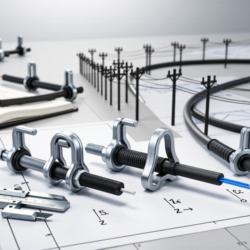
Table of Contents [Hide]
Understand the Role and Types of ADSS Clamps
ADSS clamps support all-dielectric self-supporting cables without relying on a metallic messenger. Suspension clamps hold the cable on straight pole runs, while dead-end clamps anchor it at terminals, sharp angles, or selected long spans.
Their jobs differ. A suspension unit spreads load and limits movement; a dead-end unit transfers cable tension to the pole. Some designs use protective rods to distribute pressure and reduce sheath damage.
Cable diameter, span length, line angle, wind, and ice all affect clamp selection. IEC 60794-4-20:2018 covers aerial optical cables installed along power lines, including ADSS cable. It provides a useful technical reference, but the clamp must also match the cable maker’s stated mechanical limits.
The ITU’s Facts and Figures 2023 estimated that 5.4 billion people—67% of the world’s population—were online, underscoring the need for dependable network infrastructure. That statistic does not determine clamp loads; site conditions do. And those vary.
Tips: Measure the cable diameter and check the span and angle before ordering. Confirm the clamp’s rated holding range and installation method. Avoid overtightening; concentrated pressure can deform the jacket. A detail that is easy to miss: a clamp that fits the cable may still be wrong for the span.

© Copyright - Pro Tool & Supply - Site by SVM E-Marketing Solutions - Sitemap
- Privacy policy