- Products
- Air Compressors & Air Tools
- Climate Control
- Compaction Equipment
- Concrete Cutting Tools & Equipment
- Concrete and Masonry
- Demolition & Excavation
- Electrical & Mechanical
- Fasteners and Anchoring Adhesives
- Floor Protection
- Generators and Welders
- Hand Tools
- Heaters
- Janitorial and Office Supplies
- Jobsite Protection
- Ladders & Storage
- Lighting & Lighting Accessories
- Man Lifts
- Material Handling Equipment
- Power Tools
- Pressure Washers & Pumps
- Safety Gear
- Safety Products
- Saws
- Surface Preparation
- SEASONAL PRODUCTS
- Rentals
- Air Compressor and Air Tool Rentals
- Climate Control Rental
- Compaction Rentals
- Concrete Equipment Rentals
- Demolition & Excavation Equipment Rentals
- Concrete Floor Grinder Rentals
- General Construction Equipment Rentals
- Generator Rentals and Welder Rentals
- Heater Rentals
- Light Tower Rentals
- Man Lift Rentals in Massachusetts and Rhode Island
- Material Handling Equipment Rentals
- Pressure Washer & Pump Rentals
- Saw Rentals in New England
- SEASONAL PRODUCTS
- Products
- Air Compressors & Air Tools
- Climate Control
- Compaction Equipment
- Concrete Cutting Tools & Equipment
- Demolition & Excavation
- Electrical & Mechanical
- Floor Protection
- Generators and Welders
- Construction Heaters
- Construction Ladders, Staging, & Storage
- Construction Lighting
- Man Lifts
- Material Handling Equipment
- Industrial Janitorial and Office Supplies
- Pressure Washers & Pumps
- Construction Safety Products
- Construction Safety Gear
- Surface Preparation
- Building Protection
- Diesel Accessories
- Zero Emissions
- Rentals
- Air Compressor and Air Tool Rentals
- Climate Control Rental
- Compaction Rentals
- Concrete Equipment Rental
- Demolition & Excavation Equipment Rental
- General Construction Equipment Rental
- Generator Rentals and Welder Rentals
- Construction Heaters Rental
- Light Tower Rentals
- Man Lift Rentals
- Material Handling Equipment Rental
- Pressure Washer & Pump Rentals
- Saw Rentals in New England
- Concrete Floor Grinder Rentals
- Zero Emissions Rentals
- Repairs & Used
- Parts
- Blog
- Services
- Resources
- About Us
- Contact Us
Sales & Rental of Construction | Industrial Equipment & Supplies


How to Choose ABB Power Factor Correction Capacitors
Choosing Abb Power Factor Correction Capacitors requires more than matching a kvar value to a motor rating. Power factor affects transformer loading, cable capacity, voltage stability, and utility charges. The U.S. Department of Energy identifies motor-driven equipment as responsible for a significant share of industrial electricity use, making efficient motor-system design commercially important. However, capacitors do not automatically reduce every form of energy loss.
A reliable selection process begins with measured operating data. Record real power, reactive power, voltage, current, load variation, and harmonic distortion at the main switchboard. A capacitor bank sized from a nameplate alone may perform poorly when production changes. ABB technical guidance and IEC 60831 requirements emphasize suitable voltage ratings, discharge devices, switching conditions, and thermal performance. These details matter inside a hot electrical room, where dust, poor ventilation, and frequent switching can shorten service life.
Harmonics require particular attention. The IEEE 519 standard provides recommended practices for harmonic control, while modern variable-speed drives can create conditions that make ordinary capacitors unsuitable. Detuned reactors or specialized harmonic-rated banks may be necessary. An incorrect capacitor can amplify resonance rather than solve a power-quality problem.
Field assessments often reveal another weakness: maintenance records are incomplete. That makes future decisions less certain. A practical specification should define target power factor, step control, enclosure conditions, protection, discharge time, and monitoring requirements. ABB Power Factor Correction Capacitors can support dependable system performance, but only when selected against measured conditions and verified after installation. The final design should be reviewed by a qualified electrical professional, especially in facilities with generators, drives, or rapidly changing loads.
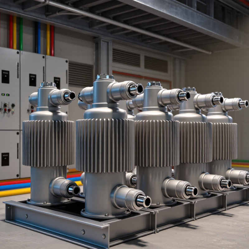
Table of Contents [Hide]
Understanding ABB Power Factor Correction Capacitor Fundamentals
Power factor correction capacitors supply reactive power close to inductive loads. Motors, transformers, and welding equipment often create this demand. The capacitor reduces current flowing through upstream cables and transformers. That can lower losses and release useful system capacity. The basic sizing value is kVAr, not physical size. Measure load current, voltage, operating hours, and power factor before selecting a unit. A clamp meter and power-quality analyzer reveal conditions that nameplate data can miss. Capacitor voltage rating should exceed normal operating voltage. Frequency also matters, because reactance changes with frequency.
Harmonics require careful attention. Capacitors can interact with system inductance and create resonance. In facilities with variable-speed drives, detuned reactors may provide safer correction. Check switching steps, discharge resistors, enclosure temperature, and ventilation. Heat shortens capacitor life, especially inside crowded panels. In practical installations, loose terminals and dust cause more trouble than expected. Torque connections according to the equipment instructions. Leave space for inspection and replacement. A neat calculation can still fail. Real loads change during shifts, and a fixed capacitor bank may overcorrect at light load. Automatic controllers usually respond better, but their settings need verification after commissioning. Record operating voltage, current, temperature, and harmonic distortion during normal production. Then compare those readings with the design assumptions. Perfect data is uncommon. Good engineering includes questioning the gaps.

© Copyright - Pro Tool & Supply - Site by SVM E-Marketing Solutions - Sitemap
- Privacy policy