- Products
- Air Compressors & Air Tools
- Climate Control
- Compaction Equipment
- Concrete Cutting Tools & Equipment
- Concrete and Masonry
- Demolition & Excavation
- Electrical & Mechanical
- Fasteners and Anchoring Adhesives
- Floor Protection
- Generators and Welders
- Hand Tools
- Heaters
- Janitorial and Office Supplies
- Jobsite Protection
- Ladders & Storage
- Lighting & Lighting Accessories
- Man Lifts
- Material Handling Equipment
- Power Tools
- Pressure Washers & Pumps
- Safety Gear
- Safety Products
- Saws
- Surface Preparation
- SEASONAL PRODUCTS
- Rentals
- Air Compressor and Air Tool Rentals
- Climate Control Rental
- Compaction Rentals
- Concrete Equipment Rentals
- Demolition & Excavation Equipment Rentals
- Concrete Floor Grinder Rentals
- General Construction Equipment Rentals
- Generator Rentals and Welder Rentals
- Heater Rentals
- Light Tower Rentals
- Man Lift Rentals in Massachusetts and Rhode Island
- Material Handling Equipment Rentals
- Pressure Washer & Pump Rentals
- Saw Rentals in New England
- SEASONAL PRODUCTS
- Products
- Air Compressors & Air Tools
- Climate Control
- Compaction Equipment
- Concrete Cutting Tools & Equipment
- Demolition & Excavation
- Electrical & Mechanical
- Floor Protection
- Generators and Welders
- Construction Heaters
- Construction Ladders, Staging, & Storage
- Construction Lighting
- Man Lifts
- Material Handling Equipment
- Industrial Janitorial and Office Supplies
- Pressure Washers & Pumps
- Construction Safety Products
- Construction Safety Gear
- Surface Preparation
- Building Protection
- Diesel Accessories
- Zero Emissions
- Rentals
- Air Compressor and Air Tool Rentals
- Climate Control Rental
- Compaction Rentals
- Concrete Equipment Rental
- Demolition & Excavation Equipment Rental
- General Construction Equipment Rental
- Generator Rentals and Welder Rentals
- Construction Heaters Rental
- Light Tower Rentals
- Man Lift Rentals
- Material Handling Equipment Rental
- Pressure Washer & Pump Rentals
- Saw Rentals in New England
- Concrete Floor Grinder Rentals
- Zero Emissions Rentals
- Repairs & Used
- Parts
- Blog
- Services
- Resources
- About Us
- Contact Us
Sales & Rental of Construction | Industrial Equipment & Supplies


How to Choose a Three Phase RCBO in 2026?
Choosing a Three Phase Rcbo in 2026 is not simply a matter of matching voltage and current. The device must protect people, cables, motors, and equipment within a real installation. A workshop may have dust, long cable runs, frequent motor starts, and uneven loads. Each detail can affect tripping performance. Mike Holt, a respected electrical educator, says, “Safety is not expensive, it’s priceless.” That principle belongs at the center of every RCBO decision.
This guide explains how to compare rated current, breaking capacity, residual operating current, pole configuration, and trip characteristics. It also considers Type A, Type F, and Type B residual-current protection. Modern equipment can create pulsed or smooth DC leakage. A basic Type AC device may not provide suitable protection in every application. Always check the manufacturer’s technical data and the electrical design requirements. Local regulations and inspection practices still matter.
Small details matter.
A reliable selection also requires checking neutral switching, enclosure temperature, busbar compatibility, terminal capacity, and available fault current. Certification should be traceable, not merely printed on a sales page. Installation testing must confirm insulation resistance, polarity, loop impedance, and residual-current operation. However, product selection alone cannot guarantee safety. Incorrect wiring, poor torque, or skipped testing can defeat a high-quality Three Phase Rcbo. This is where experience becomes important. Even experienced designers can overlook harmonic currents or future load changes. That uncertainty deserves honest review before purchase.
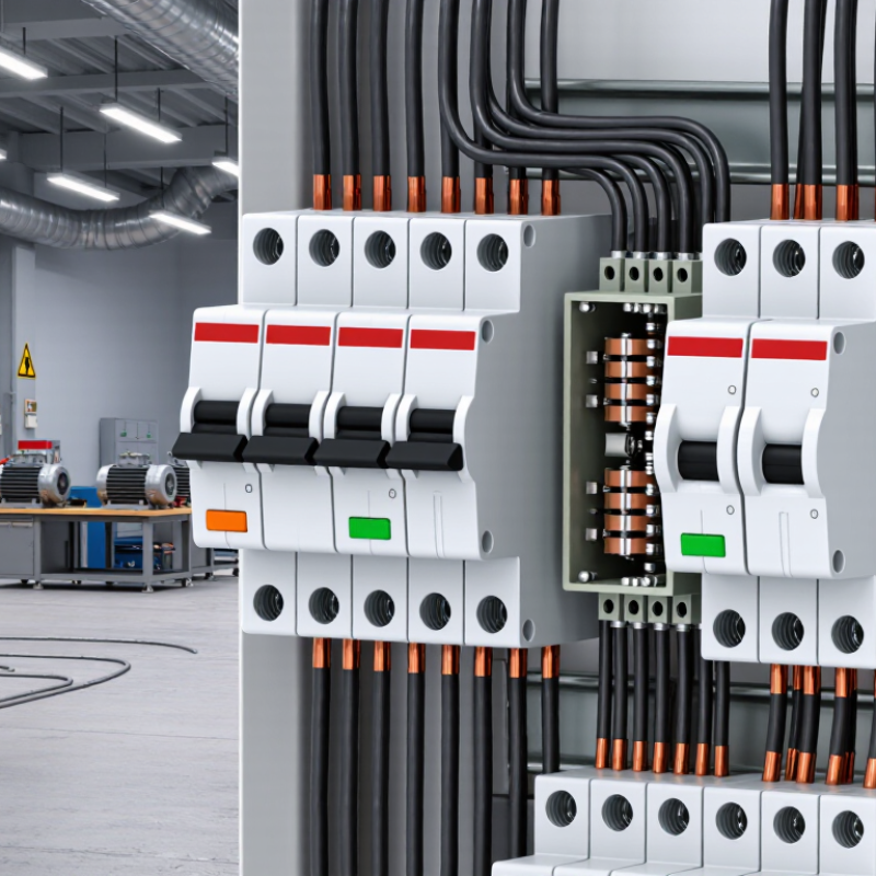
Table of Contents [Hide]
What Is a Three-Phase RCBO and How Does It Work?
A three-phase RCBO combines residual current protection with overload and short-circuit protection. It is commonly used in three-phase distribution boards and industrial circuits. Unlike a single-phase device, it monitors three live conductors, and often the neutral conductor too. The RCBO checks whether the outgoing and returning currents remain balanced.
Under normal conditions, magnetic fields inside its sensing core cancel each other. If damaged insulation allows current to flow toward earth, the balance changes. The RCBO detects this residual current and trips quickly.
Its overcurrent section responds differently. A thermal element handles sustained overloads, while a magnetic element reacts to severe short circuits. Both functions operate inside one compact unit.
A suitable three-phase RCBO must match the system voltage, frequency, pole arrangement, rated current, and residual trip sensitivity. Confirm whether the circuit requires neutral switching. Check the prospective fault current against the device rating. During commissioning, press the test button and verify that every required pole disconnects. A test button is useful, but it does not prove every installation is safe.
In practice, cable size, load balance, earthing, and enclosure temperature affect performance. I would not select the device from current rating alone. That shortcut looks efficient, yet it can hide coordination problems. Manufacturer instructions and local electrical requirements still need careful review by a qualified professional.

© Copyright - Pro Tool & Supply - Site by SVM E-Marketing Solutions - Sitemap
- Privacy policy