- Products
- Air Compressors & Air Tools
- Climate Control
- Compaction Equipment
- Concrete Cutting Tools & Equipment
- Concrete and Masonry
- Demolition & Excavation
- Electrical & Mechanical
- Fasteners and Anchoring Adhesives
- Floor Protection
- Generators and Welders
- Hand Tools
- Heaters
- Janitorial and Office Supplies
- Jobsite Protection
- Ladders & Storage
- Lighting & Lighting Accessories
- Man Lifts
- Material Handling Equipment
- Power Tools
- Pressure Washers & Pumps
- Safety Gear
- Safety Products
- Saws
- Surface Preparation
- SEASONAL PRODUCTS
- Rentals
- Air Compressor and Air Tool Rentals
- Climate Control Rental
- Compaction Rentals
- Concrete Equipment Rentals
- Demolition & Excavation Equipment Rentals
- Concrete Floor Grinder Rentals
- General Construction Equipment Rentals
- Generator Rentals and Welder Rentals
- Heater Rentals
- Light Tower Rentals
- Man Lift Rentals in Massachusetts and Rhode Island
- Material Handling Equipment Rentals
- Pressure Washer & Pump Rentals
- Saw Rentals in New England
- SEASONAL PRODUCTS
- Products
- Air Compressors & Air Tools
- Climate Control
- Compaction Equipment
- Concrete Cutting Tools & Equipment
- Demolition & Excavation
- Electrical & Mechanical
- Floor Protection
- Generators and Welders
- Construction Heaters
- Construction Ladders, Staging, & Storage
- Construction Lighting
- Man Lifts
- Material Handling Equipment
- Industrial Janitorial and Office Supplies
- Pressure Washers & Pumps
- Construction Safety Products
- Construction Safety Gear
- Surface Preparation
- Building Protection
- Diesel Accessories
- Zero Emissions
- Rentals
- Air Compressor and Air Tool Rentals
- Climate Control Rental
- Compaction Rentals
- Concrete Equipment Rental
- Demolition & Excavation Equipment Rental
- General Construction Equipment Rental
- Generator Rentals and Welder Rentals
- Construction Heaters Rental
- Light Tower Rentals
- Man Lift Rentals
- Material Handling Equipment Rental
- Pressure Washer & Pump Rentals
- Saw Rentals in New England
- Concrete Floor Grinder Rentals
- Zero Emissions Rentals
- Repairs & Used
- Parts
- Blog
- Services
- Resources
- About Us
- Contact Us
Sales & Rental of Construction | Industrial Equipment & Supplies


Why Choose a Powerline Transformer for Your Project?
A Powerline Transformer is more than a box between a generator and a load. It sets voltage levels, supports reliable service, and influences a project’s cost for decades. Choosing one means matching electrical performance to real operating conditions. Think about peak demand, expected load growth, fault levels, installation space, and the utility connection. A unit that looks adequate on a specification sheet may run hot during repeated summer peaks. That detail matters.
Transformer engineering author John J. Winders, whose book Power Transformers: Principles and Applications is a technical reference, offers a useful design perspective. In paraphrase: “A transformer must be selected for the system it serves, not just its nameplate rating.” This is a guiding principle, not a verified verbatim quotation. For project teams, it means checking voltage ratio, impedance, insulation class, cooling method, and protection requirements together. Ask how the transformer will behave at partial load, during faults, and after years of exposure to dust, moisture, or temperature swings. Small details count. A few extra centimeters of clearance can simplify inspection; poor access can complicate routine maintenance. There is no perfect choice, and oversized equipment can bring avoidable expense and losses. Still, cutting capacity too closely may leave little room for growth. A sound selection balances efficiency, resilience, budget, and serviceability. The sections that follow examine these trade-offs and show what to verify before ordering a Powerline Transformer for your project.
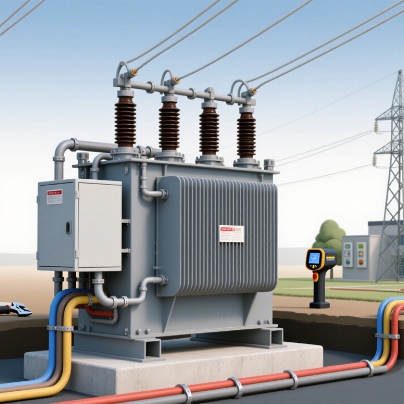
Table of Contents [Hide]
What Is a Powerline Transformer?
A powerline transformer transfers electrical energy between circuits through electromagnetic induction. Its windings surround a magnetic core, allowing voltage to change without a direct electrical connection between the circuits. It does not create energy. Some powerline transformers step voltage up for efficient transmission; others step it down for distribution to buildings and equipment. That distinction matters. The right type depends on where the transformer sits in the system and what the project needs.
A useful selection starts with the expected load, input and output voltages, phase, and frequency. Engineers also consider peak demand, impedance, cooling, insulation, and the installation environment. A unit beside a dusty industrial site may need different protection than one in a ventilated indoor room. Heat matters. So do clearances and maintenance access. A nameplate calculation is a good starting point, but real operating conditions can change the picture. Reviewing load data and site details with a qualified electrical professional helps expose those gaps before equipment is specified. The first estimate is rarely the whole story.

© Copyright - Pro Tool & Supply - Site by SVM E-Marketing Solutions - Sitemap
- Privacy policy