- Products
- Air Compressors & Air Tools
- Climate Control
- Compaction Equipment
- Concrete Cutting Tools & Equipment
- Concrete and Masonry
- Demolition & Excavation
- Electrical & Mechanical
- Fasteners and Anchoring Adhesives
- Floor Protection
- Generators and Welders
- Hand Tools
- Heaters
- Janitorial and Office Supplies
- Jobsite Protection
- Ladders & Storage
- Lighting & Lighting Accessories
- Man Lifts
- Material Handling Equipment
- Power Tools
- Pressure Washers & Pumps
- Safety Gear
- Safety Products
- Saws
- Surface Preparation
- SEASONAL PRODUCTS
- Rentals
- Air Compressor and Air Tool Rentals
- Climate Control Rental
- Compaction Rentals
- Concrete Equipment Rentals
- Demolition & Excavation Equipment Rentals
- Concrete Floor Grinder Rentals
- General Construction Equipment Rentals
- Generator Rentals and Welder Rentals
- Heater Rentals
- Light Tower Rentals
- Man Lift Rentals in Massachusetts and Rhode Island
- Material Handling Equipment Rentals
- Pressure Washer & Pump Rentals
- Saw Rentals in New England
- SEASONAL PRODUCTS
- Products
- Air Compressors & Air Tools
- Climate Control
- Compaction Equipment
- Concrete Cutting Tools & Equipment
- Demolition & Excavation
- Electrical & Mechanical
- Floor Protection
- Generators and Welders
- Construction Heaters
- Construction Ladders, Staging, & Storage
- Construction Lighting
- Man Lifts
- Material Handling Equipment
- Industrial Janitorial and Office Supplies
- Pressure Washers & Pumps
- Construction Safety Products
- Construction Safety Gear
- Surface Preparation
- Building Protection
- Diesel Accessories
- Zero Emissions
- Rentals
- Air Compressor and Air Tool Rentals
- Climate Control Rental
- Compaction Rentals
- Concrete Equipment Rental
- Demolition & Excavation Equipment Rental
- General Construction Equipment Rental
- Generator Rentals and Welder Rentals
- Construction Heaters Rental
- Light Tower Rentals
- Man Lift Rentals
- Material Handling Equipment Rental
- Pressure Washer & Pump Rentals
- Saw Rentals in New England
- Concrete Floor Grinder Rentals
- Zero Emissions Rentals
- Repairs & Used
- Parts
- Blog
- Services
- Resources
- About Us
- Contact Us
Sales & Rental of Construction | Industrial Equipment & Supplies


How to Choose a Peel Tensile Testing Machine?
Choosing a Peel Tensile Testing Machine requires more than comparing load capacity and digital displays. The right system must reproduce the real separation process of your product. Consider peel angle, test speed, specimen width, fixture design, and measurement range. A machine that performs well on thin packaging film may be unsuitable for medical tapes or laminated panels. Small differences matter.
Dr. Steve Abbott, an established adhesion scientist, states, “Adhesion is not a property of a material, it is a property of a system.” This principle should guide every purchasing decision. A reliable Peel Tensile Testing Machine must match the adhesive, substrate, backing, and testing environment. Check whether the equipment supports standardized methods such as ASTM or ISO procedures. Confirm its calibration records, software controls, emergency protection, and service availability. Ask how easily operators can replace grips or align samples.
Practical details often reveal more than a product brochure. Picture a technician preparing a 25-millimeter strip beside a temperature-controlled chamber. Can the machine hold the specimen straight? Can it record a stable force curve without noise? Can different operators repeat the same setup? These questions expose weaknesses early. No machine is perfect. Even advanced systems can produce misleading results when samples are uneven, contaminated, or poorly conditioned. That part is easy to overlook.
This guide explains how to compare machines with greater confidence. It focuses on test accuracy, laboratory workflow, compliance, durability, and long-term value. A careful choice protects both product quality and engineering decisions.
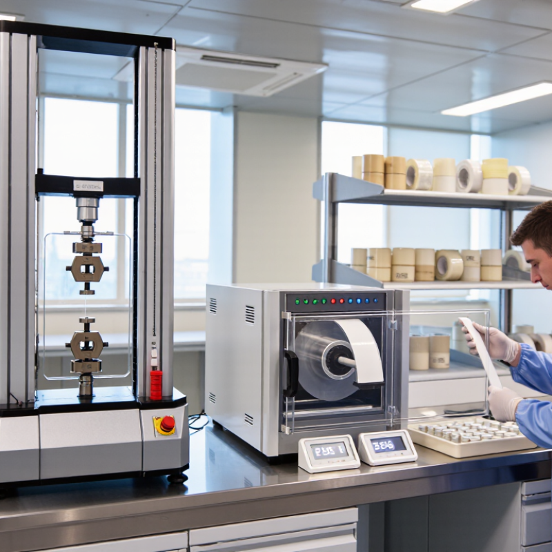
Table of Contents [Hide]
Define the Peel Testing Requirements and Material Properties
How to Choose a Peel Tensile Testing Machine?
Define the Peel Testing Requirements and Material Properties
Start with the failure you need to measure. A pouch seal, adhesive label, and laminated film behave differently. Record material thickness, coating type, seal width, peel angle, and expected force range. ASTM F88/F88M provides seal-strength methods, while ISO 8510-1 and ISO 8510-2 address 180-degree and 90-degree peel testing. These standards also show why angle and speed cannot be chosen casually.
Select a machine that matches the test method, not only the sample size. ASTM D1876 uses a T-peel configuration and commonly specifies a 254 mm/min test speed. Many adhesive tests use 300 mm/min, but the current standard edition must be checked. A 10 N load cell may suit light films, while heavier laminates may require 500 N or more. Keep the expected force near the load cell’s working range. Excess capacity can reduce resolution.
In practical lab work, I would test five specimens first. Plot the average, minimum, maximum, and peel curve. A neat average can hide a weak start or sudden seal failure. That matters. One trial may show 12 N, but the curve may fall to 4 N near the corner. I would also question conditioning time, jaw alignment, and grip slippage. These details are often overlooked. ASTM and ISO procedures improve reliability, yet real production materials can remain inconsistent. A machine with adjustable speed, interchangeable grips, suitable travel, and calibrated force measurement supports better decisions.
How to Choose a Peel Tensile Testing Machine? - Define the Peel Testing Requirements and Material Properties
| Testing Requirement | Material or Application Example | Recommended Specification | Why It Matters | Key Selection Notes |
|---|---|---|---|---|
| 1. Define the Test Method and Specimen Configuration | ||||
| Peel angle | Adhesive tape, labels, flexible laminates, bonded films | 90° or 180° peel fixtures, selected according to the applicable test procedure | The peel angle changes the force distribution and can significantly affect the measured peel resistance. | Use a dedicated fixture that maintains a stable angle throughout the test. Do not compare results from different angles without clear reporting. |
| Peel direction | Coated films, laminates, protective liners | Controlled peel direction with specimen alignment guides | Misalignment can introduce shear or bending, producing artificially high or unstable results. | Choose a machine with rigid grips, a centered load path, and an adjustable fixture position. |
| Specimen width | Strips, tapes, flexible packaging, medical adhesive assemblies | Common specimen widths include 12.5 mm, 25 mm, and 50 mm; the fixture should match the required width | Peel force may be reported as total force or force per unit width. Width consistency is essential for comparison. | Use a specimen cutter and grips that prevent edge damage, wrinkling, and lateral movement. |
| Peel length | Short bonded tabs or long continuous adhesive joints | Set a travel capacity that accommodates the initial bond length, peel distance, and any slack in the specimen | A sufficient travel range allows the machine to capture the complete peel event and a representative steady-state region. | Allow extra travel beyond the nominal peel length for setup, grip movement, and data stabilization. |
| 2. Match the Machine to Material Properties | ||||
| Expected peel force | Low-tack labels, pressure-sensitive tapes, rubber-based seals, strong laminates | Select a load cell so the expected peak force is preferably within approximately 10% to 90% of its rated capacity | Using an appropriately sized load cell improves measurement resolution while reducing the risk of overload. | Estimate the maximum force before testing. Consider startup peaks, bond defects, and specimen variability. |
| Force range | Materials with widely varying adhesion levels | Interchangeable load cells or a broad but suitable measurement range | One load cell may not provide adequate accuracy for both very low-force and high-force specimens. | Verify the rated accuracy, resolution, overload protection, and calibration range for each load cell. |
| Material elongation | Stretchable films, elastomeric layers, soft packaging materials | Long travel capability with a suitable extension or displacement measurement system | Highly extensible materials require additional travel and may store elastic energy during peeling. | Use secure grips and shielding where necessary. Check that the machine frame remains rigid under the expected load. |
| Material stiffness | Paperboard, coated metal sheets, rigid plastic laminates | High-stiffness fixtures with adequate clearance and controlled specimen bending | Rigid backings can change the peel geometry and may require special support to maintain a consistent test angle. | Confirm that the fixture can hold the backing without slipping, crushing, or introducing unintended bending. |
| Adhesive behavior | Viscoelastic pressure-sensitive adhesives and hot-melt adhesive systems | Adjustable and stable test speed, with environmental control when required | Viscoelastic adhesives are sensitive to peel rate, temperature, dwell time, and application pressure. | Record conditioning time, bonding pressure, dwell time, test speed, and test temperature with the result. |
| 3. Select Test Control and Measurement Performance | ||||
| Test speed | Standardized adhesive peel tests and comparative product development | Adjustable constant-speed control; typical methods may specify speeds such as 100 mm/min, 150 mm/min, or 300 mm/min | Peel force often changes with speed, particularly for viscoelastic adhesives and polymeric films. | Choose a system that can maintain the required speed under the expected load and allows method-specific programming. |
| Force measurement accuracy | Quality control, research testing, specification verification | Accuracy suitable for the required method and measurement range; verify calibration traceability | Peel results can be sensitive to small force changes, especially for low-tack materials. | Review the complete accuracy statement, including zero stability, repeatability, resolution, and calibration procedure. |
| Data sampling rate | Materials showing irregular peel, stick-slip, or sudden bond failure | A sampling rate high enough to capture peak force and force fluctuations at the selected test speed | Insufficient sampling can miss short-duration peaks and distort the calculated average peel force. | Use raw force-versus-displacement data where possible, rather than relying only on a single peak value. |
| Data reduction | Routine testing with a defined steady-state peel region | Software capable of calculating peak, minimum, average, and force-per-width values over a selected interval | Peel curves commonly include startup effects and local variations that should be separated from the representative region. | Define the evaluation distance consistently and exclude grip engagement or initial slack from the reported average. |
| Displacement measurement | Long peel tests, extensible specimens, deformation-sensitive applications | Appropriate crosshead or extensometer displacement measurement, depending on the required accuracy | Crosshead movement may include machine compliance and specimen deformation, so it is not always equal to true peel-front displacement. | Use the measurement method specified by the test procedure and report the displacement basis clearly. |
| 4. Account for Test Conditions and Practical Operation | ||||
| Temperature and humidity | Water-based adhesives, medical tapes, packaging films, hygroscopic papers | Environmental chamber or controlled laboratory conditions when the material is humidity- or temperature-sensitive | Adhesion, flexibility, backing stiffness, and adhesive viscosity can change with environmental conditions. | Condition specimens before testing and document temperature, relative humidity, conditioning duration, and chamber stability. |
| Conditioning and dwell time | Pressure-sensitive adhesives and laminated structures | Test workflow that supports controlled application pressure and defined dwell intervals | Bond formation continues after application, so different dwell times may produce different peel forces. | Use a repeatable roller or pressure application method and keep the dwell time consistent across specimens. |
| Grip compatibility | Thin films, paper, textiles, foams, multilayer laminates | Interchangeable grips with suitable jaw surfaces, opening range, and clamping force | Slippage, crushing, tearing, or premature failure at the grip can invalidate the test. | Choose grip faces appropriate for the backing material and maintain a straight, wrinkle-free specimen path. |
| Safety and operator protection | High-strength bonds, brittle laminates, specimens that may snap back | Overload protection, emergency stop, guarded moving parts, and controlled return movement | Stored elastic energy and sudden specimen failure can create hazards during peeling. | Consider a protective shield, safe operating distance, and automatic test termination limits. |
| Calibration and verification | Regulated production, laboratory comparison, customer qualification | Traceable force calibration, displacement verification, and documented maintenance intervals | Regular verification helps ensure that measured peel values remain comparable over time. | Define calibration intervals based on usage, risk, and applicable quality-system requirements. |
| 5. Recommended Specification Checklist | ||||
| Minimum information to define before purchase | Any peel testing program | Test angle, specimen width, expected force range, test speed, travel distance, environmental conditions, and reporting method | Clear requirements prevent an unsuitable load cell, fixture, or control system from limiting test reliability. | Prepare a written test matrix using the highest expected force, lowest expected force, longest travel, and most demanding material condition. |
| Preferred result format | Development, quality control, and supplier comparison | Force-versus-displacement curve plus average peel force, peak force, specimen width, speed, angle, and test conditions | A complete result is more useful than a single force value because it shows instability, cohesive failure, and startup effects. | Report the number of specimens, mean, standard deviation, failure mode, and any excluded results with justification. |

© Copyright - Pro Tool & Supply - Site by SVM E-Marketing Solutions - Sitemap
- Privacy policy