- Products
- Air Compressors & Air Tools
- Climate Control
- Compaction Equipment
- Concrete Cutting Tools & Equipment
- Concrete and Masonry
- Demolition & Excavation
- Electrical & Mechanical
- Fasteners and Anchoring Adhesives
- Floor Protection
- Generators and Welders
- Hand Tools
- Heaters
- Janitorial and Office Supplies
- Jobsite Protection
- Ladders & Storage
- Lighting & Lighting Accessories
- Man Lifts
- Material Handling Equipment
- Power Tools
- Pressure Washers & Pumps
- Safety Gear
- Safety Products
- Saws
- Surface Preparation
- SEASONAL PRODUCTS
- Rentals
- Air Compressor and Air Tool Rentals
- Climate Control Rental
- Compaction Rentals
- Concrete Equipment Rentals
- Demolition & Excavation Equipment Rentals
- Concrete Floor Grinder Rentals
- General Construction Equipment Rentals
- Generator Rentals and Welder Rentals
- Heater Rentals
- Light Tower Rentals
- Man Lift Rentals in Massachusetts and Rhode Island
- Material Handling Equipment Rentals
- Pressure Washer & Pump Rentals
- Saw Rentals in New England
- SEASONAL PRODUCTS
- Products
- Air Compressors & Air Tools
- Climate Control
- Compaction Equipment
- Concrete Cutting Tools & Equipment
- Demolition & Excavation
- Electrical & Mechanical
- Floor Protection
- Generators and Welders
- Construction Heaters
- Construction Ladders, Staging, & Storage
- Construction Lighting
- Man Lifts
- Material Handling Equipment
- Industrial Janitorial and Office Supplies
- Pressure Washers & Pumps
- Construction Safety Products
- Construction Safety Gear
- Surface Preparation
- Building Protection
- Diesel Accessories
- Zero Emissions
- Rentals
- Air Compressor and Air Tool Rentals
- Climate Control Rental
- Compaction Rentals
- Concrete Equipment Rental
- Demolition & Excavation Equipment Rental
- General Construction Equipment Rental
- Generator Rentals and Welder Rentals
- Construction Heaters Rental
- Light Tower Rentals
- Man Lift Rentals
- Material Handling Equipment Rental
- Pressure Washer & Pump Rentals
- Saw Rentals in New England
- Concrete Floor Grinder Rentals
- Zero Emissions Rentals
- Repairs & Used
- Parts
- Blog
- Services
- Resources
- About Us
- Contact Us
Sales & Rental of Construction | Industrial Equipment & Supplies


Why Choose a High Quality UAV Camera Module?
When every flight depends on clear visual information, camera quality becomes a practical safety factor. A high quality Uav Camera Module does more than capture attractive images. It helps operators recognize surface cracks, crop stress, road edges, and changing terrain. In field testing, small details matter: lens clarity at sunrise, stable frames during vibration, and clean shadows under changing light. These details influence mapping, inspection, agriculture, and emergency response. Clear evidence matters.
Quality begins with the sensor, but it does not end there. A professional module should offer suitable dynamic range, accurate colors, low-light performance, and controlled image noise. Optical stabilization can reduce blur when the aircraft moves through wind. Thermal management supports consistent operation during long missions. Reliable firmware and compatible interfaces also simplify integration with flight controllers, storage systems, and ground software. Verified test data, traceable manufacturing processes, and responsive technical support provide stronger confidence than impressive specifications alone. Experienced suppliers should explain these points clearly.
However, a higher price does not automatically mean better performance. That assumption needs testing. Buyers should compare the module with actual mission needs, payload limits, weather conditions, and required image outputs. Request sample footage, calibration information, test reports, and integration guidance before making a decision. Do not trust polished specifications alone. Even careful evaluations can miss problems after installation, especially with power compatibility or software updates. A thoughtful Uav Camera Module choice balances image quality, durability, reliability, and practical support. That balance is often more valuable than a perfect-looking product sheet.
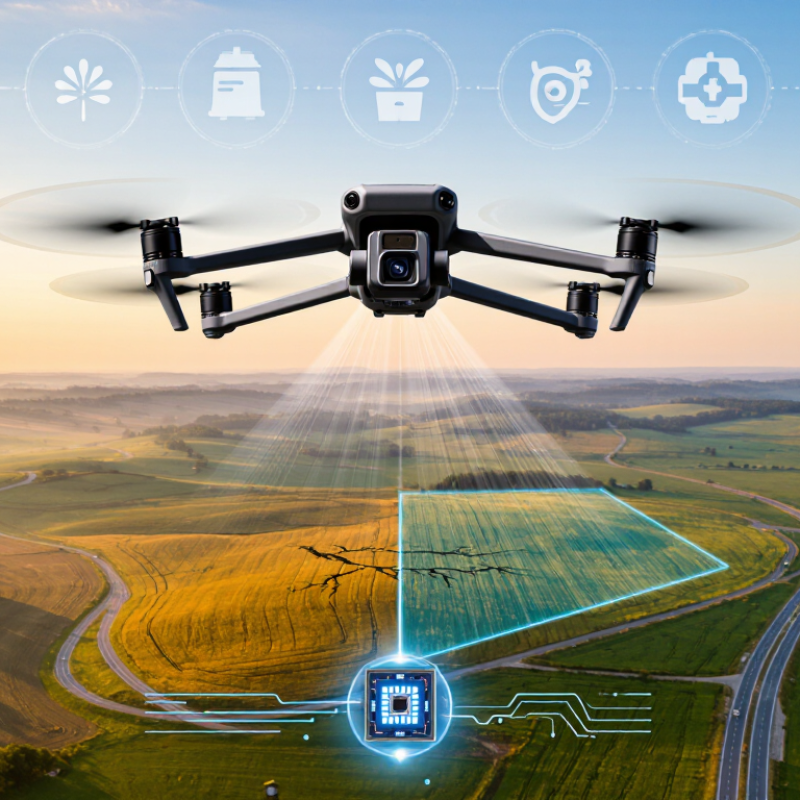
Table of Contents [Hide]
What Is a High-Quality UAV Camera Module?
A high-quality UAV camera module is more than a sensor with many pixels. It combines optical clarity, stable exposure, accurate color, and dependable mechanical design. In field inspections, a small crack may occupy only a few pixels on a bridge surface. Motion blur can erase it completely. The camera must preserve useful detail while the aircraft vibrates, changes direction, and faces uneven sunlight.
Industry data explains why this quality matters. Drone Industry Insights reported that commercial drone services continued expanding in 2024, with inspection, mapping, and surveying among the strongest application areas. Grand View Research estimated the global commercial drone market at about USD 30.6 billion in 2022, with strong growth expected through 2030. These figures suggest greater demand for trustworthy imaging, not simply cheaper hardware.
A capable module should offer high dynamic range, low distortion, precise autofocus, and effective electronic or mechanical stabilization. Thermal control also matters. A warm sensor can introduce noise during long flights.
In practical testing, engineers should compare images at dawn, noon, and under artificial light. Check edge sharpness, rolling-shutter distortion, and exposure recovery after a bright reflection. Pixel count can mislead. A 4K image with poor lenses remains weak evidence. I have also found that autofocus performance is sometimes inconsistent at long distances. That limitation deserves attention. A reliable UAV camera module needs repeatable results, clear calibration records, and protection against dust, moisture, and vibration. Certification and documented test methods further improve confidence, although no module performs perfectly in every environment.

© Copyright - Pro Tool & Supply - Site by SVM E-Marketing Solutions - Sitemap
- Privacy policy