- Products
- Air Compressors & Air Tools
- Climate Control
- Compaction Equipment
- Concrete Cutting Tools & Equipment
- Concrete and Masonry
- Demolition & Excavation
- Electrical & Mechanical
- Fasteners and Anchoring Adhesives
- Floor Protection
- Generators and Welders
- Hand Tools
- Heaters
- Janitorial and Office Supplies
- Jobsite Protection
- Ladders & Storage
- Lighting & Lighting Accessories
- Man Lifts
- Material Handling Equipment
- Power Tools
- Pressure Washers & Pumps
- Safety Gear
- Safety Products
- Saws
- Surface Preparation
- SEASONAL PRODUCTS
- Rentals
- Air Compressor and Air Tool Rentals
- Climate Control Rental
- Compaction Rentals
- Concrete Equipment Rentals
- Demolition & Excavation Equipment Rentals
- Concrete Floor Grinder Rentals
- General Construction Equipment Rentals
- Generator Rentals and Welder Rentals
- Heater Rentals
- Light Tower Rentals
- Man Lift Rentals in Massachusetts and Rhode Island
- Material Handling Equipment Rentals
- Pressure Washer & Pump Rentals
- Saw Rentals in New England
- SEASONAL PRODUCTS
- Products
- Air Compressors & Air Tools
- Climate Control
- Compaction Equipment
- Concrete Cutting Tools & Equipment
- Demolition & Excavation
- Electrical & Mechanical
- Floor Protection
- Generators and Welders
- Construction Heaters
- Construction Ladders, Staging, & Storage
- Construction Lighting
- Man Lifts
- Material Handling Equipment
- Industrial Janitorial and Office Supplies
- Pressure Washers & Pumps
- Construction Safety Products
- Construction Safety Gear
- Surface Preparation
- Building Protection
- Diesel Accessories
- Zero Emissions
- Rentals
- Air Compressor and Air Tool Rentals
- Climate Control Rental
- Compaction Rentals
- Concrete Equipment Rental
- Demolition & Excavation Equipment Rental
- General Construction Equipment Rental
- Generator Rentals and Welder Rentals
- Construction Heaters Rental
- Light Tower Rentals
- Man Lift Rentals
- Material Handling Equipment Rental
- Pressure Washer & Pump Rentals
- Saw Rentals in New England
- Concrete Floor Grinder Rentals
- Zero Emissions Rentals
- Repairs & Used
- Parts
- Blog
- Services
- Resources
- About Us
- Contact Us
Sales & Rental of Construction | Industrial Equipment & Supplies


How to Choose a Fuel Pump Motor Commutator in 2026?
In 2026, selecting a Fuel Pump Motor Commutator is not simply a matter of matching its outside diameter. A dependable choice must suit the motor’s voltage, current, speed, brush material, and operating temperature. Small differences matter. A segment count that looks close may still produce poor brush contact, excess sparking, or rapid wear. Check the commutator’s diameter, shaft fit, segment geometry, copper quality, and mica undercut against the motor’s drawings or verified sample. Then confirm the supplier’s dimensional tolerances and inspection records.
Motor-drive author Austin Hughes provides useful context for evaluating how a motor’s electrical and mechanical requirements work together. A practical paraphrase of that engineering perspective is: “Match the commutator to the motor’s real duty, not just its nominal dimensions.” This is a paraphrase, not a verbatim quotation. For fuel-pump applications, ask how the part performs under repeated starts, vibration, and heat inside the pump assembly. Request evidence from relevant endurance and electrical tests, rather than relying on a polished product sheet. Traceable materials and consistent production batches matter, too. A low price can be tempting. It is not proof of value. The awkward part is that a commutator may pass a quick visual check and still fail early in service. This guide outlines the specifications, supplier questions, and test data worth reviewing before you choose. It also leaves room for a sensible caution: no single material or dimension is best for every motor.
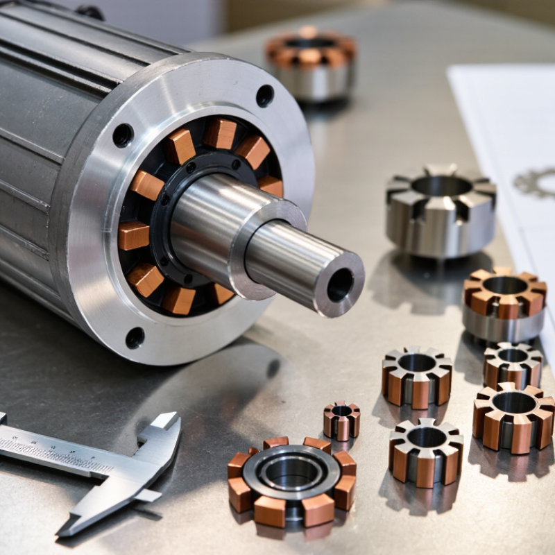
Table of Contents [Hide]
Understanding the Role of a Commutator in a Fuel Pump Motor
A commutator transfers current to a fuel pump motor’s rotating armature through contact with carbon brushes. Its copper segments switch current as the rotor turns, producing continuous rotation.
Worn segments, poor brush contact, or high resistance can cause sparking, heat, uneven torque, and a pump that struggles to maintain flow. Small parts matter here.
When choosing one, match the original diameter, segment count, shaft fit, and electrical rating. Check surface finish and segment spacing, too; rough edges can accelerate brush wear. Material and construction must tolerate vibration, heat, and repeated starts.
The U.S. Environmental Protection Agency’s 2024 Automotive Trends Report gives average new-vehicle fuel economy as 27.1 miles per gallon for model year 2023. That fleet-wide figure does not measure commutator performance, but it is a useful reminder: fuel use depends on the whole vehicle, not one motor component.
Avoid treating a larger commutator as automatically better. Compare its dimensions and operating limits with the motor specification, then inspect for discoloration or uneven wear after testing.
There is a judgment call: supplier data may not fully reflect real pump conditions. Recheck fit and current draw in the intended assembly.

© Copyright - Pro Tool & Supply - Site by SVM E-Marketing Solutions - Sitemap
- Privacy policy