- Products
- Air Compressors & Air Tools
- Climate Control
- Compaction Equipment
- Concrete Cutting Tools & Equipment
- Concrete and Masonry
- Demolition & Excavation
- Electrical & Mechanical
- Fasteners and Anchoring Adhesives
- Floor Protection
- Generators and Welders
- Hand Tools
- Heaters
- Janitorial and Office Supplies
- Jobsite Protection
- Ladders & Storage
- Lighting & Lighting Accessories
- Man Lifts
- Material Handling Equipment
- Power Tools
- Pressure Washers & Pumps
- Safety Gear
- Safety Products
- Saws
- Surface Preparation
- SEASONAL PRODUCTS
- Rentals
- Air Compressor and Air Tool Rentals
- Climate Control Rental
- Compaction Rentals
- Concrete Equipment Rentals
- Demolition & Excavation Equipment Rentals
- Concrete Floor Grinder Rentals
- General Construction Equipment Rentals
- Generator Rentals and Welder Rentals
- Heater Rentals
- Light Tower Rentals
- Man Lift Rentals in Massachusetts and Rhode Island
- Material Handling Equipment Rentals
- Pressure Washer & Pump Rentals
- Saw Rentals in New England
- SEASONAL PRODUCTS
- Products
- Air Compressors & Air Tools
- Climate Control
- Compaction Equipment
- Concrete Cutting Tools & Equipment
- Demolition & Excavation
- Electrical & Mechanical
- Floor Protection
- Generators and Welders
- Construction Heaters
- Construction Ladders, Staging, & Storage
- Construction Lighting
- Man Lifts
- Material Handling Equipment
- Industrial Janitorial and Office Supplies
- Pressure Washers & Pumps
- Construction Safety Products
- Construction Safety Gear
- Surface Preparation
- Building Protection
- Diesel Accessories
- Zero Emissions
- Rentals
- Air Compressor and Air Tool Rentals
- Climate Control Rental
- Compaction Rentals
- Concrete Equipment Rental
- Demolition & Excavation Equipment Rental
- General Construction Equipment Rental
- Generator Rentals and Welder Rentals
- Construction Heaters Rental
- Light Tower Rentals
- Man Lift Rentals
- Material Handling Equipment Rental
- Pressure Washer & Pump Rentals
- Saw Rentals in New England
- Concrete Floor Grinder Rentals
- Zero Emissions Rentals
- Repairs & Used
- Parts
- Blog
- Services
- Resources
- About Us
- Contact Us
Sales & Rental of Construction | Industrial Equipment & Supplies


China Top 10 Dual Torch Pipeline Welding Machine Brands?
China’s dual torch welding sector has developed rapidly, especially for long-distance pipeline construction and controlled workshop fabrication. This article examines China’s Top 10 Dual Torch Pipeline Welding Machine brands through practical performance, engineering capability, and service reliability. The ranking considers torch synchronization, welding speed, heat control, seam consistency, and operator safety. It also reviews compatibility with carbon steel, stainless steel, and different pipeline wall thicknesses.
Dr. John C. Lippold, a respected welding metallurgy researcher, has stated, “Welding is both a science and an art.” That observation remains relevant here. A Dual Torch Pipeline Welding Machine is not judged by speed alone. Stable arc transfer, accurate wire feeding, and balanced torch movement matter more when a joint must remain consistent for several meters. In field conditions, dust, uneven ground, voltage fluctuation, and limited maintenance support can expose weaknesses quickly.
This guide compares leading Chinese manufacturers from a buyer’s practical perspective. It considers documented specifications, production experience, quality systems, application support, and customer feedback. Some brands appear impressive on paper, yet their real performance may vary between models. No ranking is flawless. Buyers should still inspect weld samples, verify after-sales response, and request evidence from comparable pipeline projects. A lower-priced machine may reduce initial spending, but it can create costly downtime later. The best choice depends on pipe diameter, material grade, welding process, worksite conditions, and the skill level of the operating team.
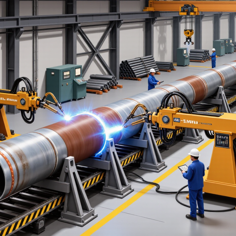
Table of Contents [Hide]
What Is a Dual-Torch Pipeline Welding Machine?
Among China’s top 10 dual-torch pipeline welding machine options, the core question is how the system works. A dual-torch pipeline welding machine is automated equipment designed to weld two sections of pipe at the same time. It uses two synchronized welding heads, controlled movement, and a shared power or process system. The torches may work on opposite sides of a joint or follow separate weld paths. This arrangement can improve productivity during repetitive pipeline fabrication. Precision matters.
In real workshops, operators first align and clamp the pipe carefully. The machine then controls travel speed, torch angle, arc length, and heat input. Sensors or preset programs can help maintain a consistent bead around the circumference. Two torches also reduce idle time when long weld seams must meet production targets. However, faster does not automatically mean better. Poor fit-up can create uneven penetration, porosity, or excessive weld buildup. Field experience shows that small alignment errors often become obvious only after inspection.
A reliable setup requires qualified welders, approved welding procedures, and routine calibration. The operator still checks gas flow, wire feeding, cooling, and torch synchronization. Inspection may include visual checks, dimensional measurement, and suitable nondestructive testing. The best machine is not always the most complex one. It should match pipe diameter, material, wall thickness, joint design, and production volume. One practical limitation is flexibility. A dual-torch system may need more setup time for unusual diameters or repairs. That trade-off deserves honest evaluation before purchase.
China Top 10 Dual Torch Pipeline Welding Machine Brands? - What Is a Dual-Torch Pipeline Welding Machine?
| No. | Data Dimension | Factual Technical Data | Why It Matters in Pipeline Welding |
|---|---|---|---|
| 1 | Definition | A dual-torch pipeline welding machine uses two welding torches mounted on one mechanized carriage or welding head to weld two areas of a pipe joint during the same operating cycle. | The two torches can work simultaneously, sequentially, or with coordinated travel, depending on the welding procedure and machine control system. |
| 2 | Main Productivity Benefit | Two torches can reduce the number of welding passes or increase deposition productivity when the qualified welding procedure permits simultaneous operation. | Actual productivity depends on pipe diameter, wall thickness, weld-process parameters, joint design, preheating, inspection requirements, and operator setup time. |
| 3 | Common Welding Processes | Typical process combinations include GMAW/MIG, FCAW, GTAW/TIG, and combinations such as GTAW for the root pass with GMAW or FCAW for fill and cap passes. | The selected process must match the approved welding procedure, base material, consumable classification, shielding-gas requirements, and required weld quality. |
| 4 | Torch Arrangement | Common layouts include two torches operating on opposite sides of the pipe circumference, two torches following one another, or two independently adjustable torches on one carriage. | Adjustable torch spacing and angle help maintain the correct arc position when pipe diameter, joint geometry, or welding sequence changes. |
| 5 | Motion Axes | A mechanized system generally controls circumferential travel and may also provide torch oscillation, wire-feed control, vertical adjustment, lateral adjustment, and automatic start/stop functions. | Independent adjustment of each torch improves control of arc length, bead placement, overlap, and heat distribution around the joint. |
| 6 | Pipe Compatibility | Compatibility is determined by the machine’s clamp or carriage design, pipe outside-diameter range, joint access, wall thickness, and maximum permissible equipment load. | There is no universal pipe-size range for all dual-torch machines; the manufacturer’s technical specification and the qualified procedure must be checked for each application. |
| 7 | Control and Synchronization | Key control functions include synchronized travel speed, individual welding-current control, voltage control, wire-feed speed, oscillation width, dwell time, and crater-fill settings. | Synchronization prevents the two torches from interfering with one another and helps maintain consistent heat input and bead geometry. |
| 8 | Heat Input Management | Heat input is affected by welding current, arc voltage, travel speed, process efficiency, torch spacing, and the number of active arcs. | Heat input must remain within the approved welding procedure range to control penetration, hardness, distortion, hydrogen-related risks, and toughness. |
| 9 | Applicable Qualification Frameworks | Pipeline welding procedures are commonly qualified under applicable requirements such as API 1104, ASME BPVC Section IX, ISO 15614-1, or project-specific specifications. Welder qualification may use ISO 9606-1 or another applicable code. | The governing code depends on the pipeline owner, jurisdiction, service conditions, material, and project contract. A machine itself does not replace procedure or welder qualification. |
| 10 | Inspection and Quality Control | Typical quality controls include visual inspection, dimensional checks, welding-parameter recording, non-destructive testing, and verification of preheat and interpass temperatures. | Common NDT methods may include radiographic testing, ultrasonic testing, magnetic particle testing, or liquid penetrant testing, selected according to the applicable code and project specification. |
Technical note: Dual-torch performance is application-dependent. Pipe diameter, material grade, wall thickness, joint design, consumables, welding procedure qualification, environmental conditions, and inspection requirements should be confirmed before equipment selection.

© Copyright - Pro Tool & Supply - Site by SVM E-Marketing Solutions - Sitemap
- Privacy policy