Sales & Rental of Construction | Industrial Equipment & Supplies

2026 Best MPO Cable Types for Data Centers?

Choosing the right MPO Cable for a data center in 2026 is not just a connector decision. It affects port density, link performance, upgrade options, and how easily technicians can trace a connection. A compact MPO trunk can carry many fibers through a crowded rack, while a breakout cable can connect an MPO interface to individual duplex ports. Small details matter.

This guide compares common options, including MPO-12 and MPO-16 assemblies, multimode OM4 and OM5, and single-mode OS2. Each fits different distances, optics, and migration plans. A dense leaf-spine network may favor parallel-fiber links; a mixed-speed environment may benefit from breakout assemblies. Neither is automatically better. Check the transceiver interface, fiber count, polarity, connector gender, insertion-loss limits, and equipment specifications before ordering. One mismatch can turn a neat installation into hours of troubleshooting.

There is no universal winner. That is inconvenient, but important. Product labels and “future-ready” claims do not replace a channel-level design review. Teams should confirm whether their applications use parallel optics or duplex links, then test representative assemblies with compatible equipment. Keep room for growth, but avoid paying for capacity the network will not use. Even experienced teams can overlook polarity or cleaning during a rushed upgrade. This comparison aims to make those trade-offs visible, so data-center planners can choose MPO cable types with clearer evidence and fewer surprises.
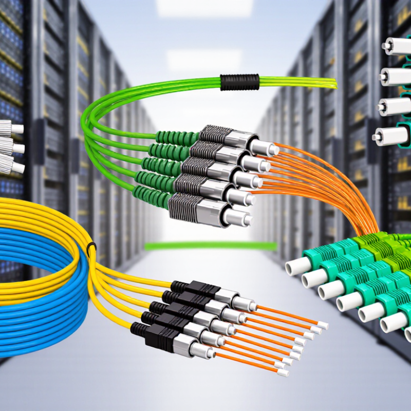
2026 Best MPO Cable Types for Data Centers?

Classify MPO Trunks by 8-, 12-, 16-, and 24-Fiber Configurations

MPO trunks are best classified by fiber count, but the number alone does not determine compatibility. Match the trunk to the transceiver, channel plan, and polarity required at both ends. A tidy fiber-count chart can hide these details.

An 8-fiber trunk commonly serves parallel-optics links using four transmit and four receive fibers, such as many SR4 connections. A 12-fiber trunk is a familiar backbone choice and may carry eight active fibers in some parallel-optics applications, leaving four unused. That spare capacity can be useful, but only when the equipment and cassette layout support it. Check the ends.

A 16-fiber trunk supports eight fiber pairs and is used with interfaces designed for eight-lane parallel transmission, including some SR8 applications. A 24-fiber trunk packs more fibers into a high-density route and can serve multiple channels through compatible cassettes or breakout assemblies. More fibers do not automatically mean better performance. Inspect connector gender, polarity, and fiber mapping before ordering; a small mismatch can leave a carefully planned link dark. Actual channel needs and migration plans should guide the choice, and those plans are sometimes less certain than a spreadsheet suggests.

Compare OM4’s 100 m IEEE 802.3 Limit for 100GBASE-SR4 with OS2

For 100GBASE-SR4, OM4 supports a maximum channel reach of 100 m under IEEE 802.3 specifications. The link uses parallel transmission across four lanes in each direction, typically over an MPO-connected fiber array. In a data-center aisle, that distance may comfortably cover a rack row. But patch panels, connectors, and installation quality all affect the usable channel.

OS2 supports single-mode applications that can reach much farther, provided the optics match. For example, 100GBASE-LR4 is specified for up to 10 km over single-mode fiber. That does not mean OS2 automatically extends an SR4 link: SR4 optics are designed for multimode fiber, so the optical interface must change too. Different optics, connectors, and testing procedures can add cost and complexity.

The trade-off is not simply short versus long. OM4 can suit compact links where 100 m is enough and compatible SR4 equipment is available. OS2 can offer room for longer runs and future link changes, but its benefit depends on the chosen transceivers. Check the complete channel design, including polarity and connector losses, before ordering MPO trunks. It is easy to overlook those details. A measured link can still expose assumptions that looked fine on a spreadsheet.

Match MPO-12 and MPO-16 Interfaces to 40G, 100G, and 400G Optics

MPO selection follows the optic’s lane layout, not headline speed alone. IEEE 802.3ba specifies 40GBASE-SR4 as four 10-Gb/s transmit lanes and four receive lanes. An MPO-12 connector carries the eight active fibers, leaving four positions unused. IEEE 802.3bm’s 100GBASE-SR4 uses the same eight-fiber pattern, with four 25-Gb/s lanes in each direction. On a patch panel, check polarity and cassette mapping before connecting the trunk.

Small detail. Big outage risk.

At 400G, connector choice depends on the optic. IEEE 802.3bs defines 400GBASE-DR4 around four 100-Gb/s lanes, typically using eight fibers through MPO-12. IEEE 802.3cm defines 400GBASE-SR8 with eight 50-Gb/s lanes in each direction and 16 fibers, matching MPO-16. The Ethernet Alliance’s 2024 Ethernet Roadmap includes 400GbE in its speed outlook, but that does not make every 400G link interchangeable.

DR4 uses single-mode fiber; SR8 uses multimode fiber. Confirm fiber type, reach, and polarity against the module specifications.

A neat MPO-16 trunk can still fail if the cassette is mapped for MPO-12. I would verify the lane map twice; field labels are not always perfect.

Check IEC 61754-7 Connector Fit, Polish Type, and Polarity

2026 Best MPO Cable Types for Data Centers?

For MPO selection, begin with connector fit, not fiber count. IEC 61754-7 defines the MPO connector interface, but compatibility still depends on pinning, guide features, and adapter alignment. A connector that looks right can fail to mate correctly. Check the equipment port and cable documentation before ordering.

Polish type matters too. Many multimode links use PC or UPC-style finishes, while single-mode links commonly specify APC. These are not interchangeable choices. Verify the transceiver and link specifications together. Polarity is equally easy to overlook: a transmit-to-receive mismatch can leave a neatly installed trunk dark. TIA-568.3-E provides cabling guidance, while the Ethernet Alliance’s 2024 roadmap tracks 800GbE and 1.6TbE developments. Higher-speed migration makes connector and polarity planning more consequential, even when the cable itself seems simple. A small detail. Sometimes the labeling is unclear, so confirm it before deployment.

Tips: Record connector gender, polish, fiber type, and polarity method on each cable schedule. Inspect endfaces before mating, and verify polarity with a tester. Don’t assume matching labels mean matching layouts; that assumption deserves a second look.

2026 Best MPO Cable Types for Data Centers? - Check IEC 61754-7 Connector Fit, Polish Type, and Polarity
MPO Cable Type Typical Data-Center Use Common Fiber Counts Connector Fit to Check Typical Polish Selection Polarity and Selection Notes
MPO trunk cable Permanent backbone links between patch panels, equipment areas, or cassette enclosures. Commonly 12 or 24 fibers; 8- and 16-fiber configurations are also used in parallel-optics systems. Check the MPO interface and fiber-count configuration against IEC 61754-7. A mating pair generally requires one connector with guide pins and one connector without guide pins. Confirm key orientation and adapter compatibility. Multimode links commonly use flat/PC end faces. Single-mode links may use APC or PC/UPC; APC and PC/UPC connectors must not be mated together. Specify the polarity method for both ends of the trunk and the connected modules. Do not assume a cable is straight-through or reversed from its appearance.
MPO-to-LC harness (breakout) cable Connects a high-density MPO backbone to individual duplex LC ports, such as at a switch or patch panel. Often 8, 12, or 24 fibers at the MPO end, with the LC leg count determined by the fiber count and design. Check the MPO connector gender, keying, fiber count, and the connector type and polish at the LC ends. The MPO mating end must match the connected adapter or port. Choose the MPO polish and LC end-face polish to match the transceivers and the rest of the link. Multimode LC ends are commonly PC; single-mode LC ends may be PC/UPC or APC. Confirm the fiber-to-LC mapping and duplex transmit/receive orientation. The harness must match the polarity plan of the trunk, adapters, and equipment.
MPO-to-MPO patch cord Short cross-connects between MPO ports, patch panels, cassettes, or equipment fitted with MPO interfaces. Commonly 8, 12, or 24 fibers; other configurations depend on the optical interface and system design. Verify IEC 61754-7 interface compatibility, connector gender at each end, key orientation, fiber count, and adapter type. A pinned connector should mate with an unpinned connector. Use the polish required by the connected ports. Do not connect APC to PC/UPC, even when the connector body fits. Choose the cord polarity only after checking the complete link. Type A, Type B, and Type C arrangements have different fiber mappings.
MPO-to-LC cassette feed cable Feeds an MPO-terminated backbone into a cassette that presents duplex LC ports for equipment connections. Frequently 12 or 24 fibers, depending on the cassette design and the number of LC duplex ports. Match the MPO gender, keying, fiber count, and polish to the cassette input. Confirm that the cassette is designed for the selected MPO format. Match the MPO and LC interfaces to the installed optical channel; do not infer polish from fiber count or connector color alone. Check the cassette’s internal fiber mapping as well as the feed-cable polarity. Verify that each equipment transmit path connects to the intended receive path.
High-fiber-count MPO backbone cable High-density links for parallel optics or multiple channels between data-center zones and distribution frames. Often built from multiple MPO interfaces or higher-count configurations; select the count to match the optical system and panel layout. Confirm the exact connector format and interface variant, fiber count, keying, gender, and adapter fit. IEC 61754-7 covers MPO interface requirements; the cable assembly must also suit the installed system. Polish depends on the optical application and connected equipment. Keep polish type consistent across every mating interface. Document each MPO position and polarity path. Validate the complete channel with the intended modules and patching components before deployment.
Polarity reference: In commonly used MPO cabling methods, Method A maps fiber position 1 to position 1, Method B reverses the position order, and Method C flips adjacent fiber pairs. These describe cable mapping, not connector polish or gender. Select a consistent end-to-end design and verify it against the transceiver and cabling-system requirements. IEC 61754-7 addresses MPO connector interfaces; it does not by itself specify the performance of a complete cable link.

Choose Trunks, Harnesses, or Cassettes by Loss Budget and Migration Needs

MPO trunks suit permanent links between data-center zones, especially when parallel optics use dense, multi-fiber connections. They reduce cable bulk across overhead pathways. Specify fiber count, polarity, and connector gender before ordering; a mismatch can stop a link from coming up. Keep slack accessible, not crushed above the rack.

Harnesses branch an MPO trunk into duplex connectors near switches or servers. They work well when equipment uses LC ports and space is tight. Cassettes offer a more modular transition: plug the trunk into a panel, then connect equipment with short duplex patch cords. That flexibility has a cost. Each added connection contributes insertion loss. Small details matter.

Choose by the measured loss budget, not by panel density alone. Check transceiver limits, cable length, connector count, and the loss figures for every mated pair. Clean and inspect end faces before testing; dust can consume margin quickly. For migration, map the current polarity and port layout, then test a sample link before replacing a full row. That step can feel slow, and the plan may still need revision. Yet it helps reveal whether trunks, harnesses, or cassettes fit the actual equipment and future changes.

2026 Best MPO Cable Types for Data Centers: Trunks, Harnesses, or Cassettes?

Illustrative insertion-loss estimate for representative link layouts

Estimates use a planning allowance of 0.35 dB per mated connector pair: trunks and harnesses are modeled with two pairs (0.70 dB), while a cassette-based link is modeled with two MPO and two equipment-side pairs (1.40 dB). These are illustrative topology estimates, not guaranteed component or channel limits. Actual loss depends on connector grade, polarity, link layout, and equipment interfaces; verify the complete channel against the application loss budget. Trunks suit direct, low-complexity runs; harnesses support breakout connections; cassettes simplify cross-connects and future migration.

© Copyright - Pro Tool & Supply - Site by SVM E-Marketing Solutions - Sitemap - Privacy policy
