- Products
- Air Compressors & Air Tools
- Climate Control
- Compaction Equipment
- Concrete Cutting Tools & Equipment
- Concrete and Masonry
- Demolition & Excavation
- Electrical & Mechanical
- Fasteners and Anchoring Adhesives
- Floor Protection
- Generators and Welders
- Hand Tools
- Heaters
- Janitorial and Office Supplies
- Jobsite Protection
- Ladders & Storage
- Lighting & Lighting Accessories
- Man Lifts
- Material Handling Equipment
- Power Tools
- Pressure Washers & Pumps
- Safety Gear
- Safety Products
- Saws
- Surface Preparation
- SEASONAL PRODUCTS
- Rentals
- Air Compressor and Air Tool Rentals
- Climate Control Rental
- Compaction Rentals
- Concrete Equipment Rentals
- Demolition & Excavation Equipment Rentals
- Concrete Floor Grinder Rentals
- General Construction Equipment Rentals
- Generator Rentals and Welder Rentals
- Heater Rentals
- Light Tower Rentals
- Man Lift Rentals in Massachusetts and Rhode Island
- Material Handling Equipment Rentals
- Pressure Washer & Pump Rentals
- Saw Rentals in New England
- SEASONAL PRODUCTS
- Products
- Air Compressors & Air Tools
- Climate Control
- Compaction Equipment
- Concrete Cutting Tools & Equipment
- Demolition & Excavation
- Electrical & Mechanical
- Floor Protection
- Generators and Welders
- Construction Heaters
- Construction Ladders, Staging, & Storage
- Construction Lighting
- Man Lifts
- Material Handling Equipment
- Industrial Janitorial and Office Supplies
- Pressure Washers & Pumps
- Construction Safety Products
- Construction Safety Gear
- Surface Preparation
- Building Protection
- Diesel Accessories
- Zero Emissions
- Rentals
- Air Compressor and Air Tool Rentals
- Climate Control Rental
- Compaction Rentals
- Concrete Equipment Rental
- Demolition & Excavation Equipment Rental
- General Construction Equipment Rental
- Generator Rentals and Welder Rentals
- Construction Heaters Rental
- Light Tower Rentals
- Man Lift Rentals
- Material Handling Equipment Rental
- Pressure Washer & Pump Rentals
- Saw Rentals in New England
- Concrete Floor Grinder Rentals
- Zero Emissions Rentals
- Repairs & Used
- Parts
- Blog
- Services
- Resources
- About Us
- Contact Us
Sales & Rental of Construction | Industrial Equipment & Supplies


What Is a Battery Management System PCB?
A Battery Management System PCB (BMS PCB) is the control center inside a modern battery pack. It connects sensors, protection circuits, communication interfaces, and power-management components. Together, these parts monitor voltage, current, temperature, and charging conditions. The board may be compact, but its responsibilities are substantial. A weak measurement path can distort the entire safety decision.
Davide Andrea, author of Battery Management Systems for Large Lithium-Ion Battery Packs, describes the BMS as “the brain of the battery pack.” This comparison is useful, although incomplete. The PCB also acts like a nervous system and a safety gate. It collects signals from individual cells, balances charge levels, and can disconnect the pack during abnormal operation. In an electric vehicle, it may monitor dozens or hundreds of cells while communicating with the vehicle controller.
Design details matter. Engineers must consider insulation spacing, heat near switching devices, connector reliability, and electromagnetic interference. A clean schematic does not guarantee a reliable product. Real packs experience vibration, moisture, aging cells, and imperfect assembly. Testing must reflect those conditions.
The topic is not only about circuit diagrams. It concerns measurement accuracy, fault handling, thermal behavior, and serviceability. Even experienced designers can overlook a small failure path. That is why a trustworthy BMS PCB requires documented requirements, controlled production, and repeated validation. Its performance should be judged under normal use and credible fault conditions. The design may never be perfect, but it must fail predictably.
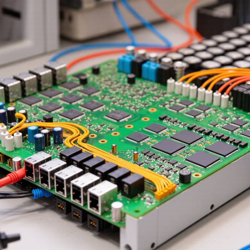
Table of Contents [Hide]
Definition and Purpose of a Battery Management System PCB
What Is a Battery Management System PCB?
A Battery Management System PCB is the circuit board that monitors and controls a rechargeable battery pack. It connects sensing circuits, protection components, communication interfaces, and the control processor. Its purpose is not simply to “manage” power. It measures each cell’s voltage, pack current, and temperature during charging and discharging.
When a cell reaches an unsafe limit, the PCB can interrupt the circuit through electronic switches. It may also balance cells by removing small amounts of excess energy from stronger cells. This keeps cell voltages closer together. A reliable design reduces overcharging, deep discharge, overheating, and unexpected shutdowns. Small details matter. A misplaced temperature sensor can delay a protective response.
The PCB also provides useful information to external equipment. It can report remaining capacity, fault conditions, charge cycles, and operating temperature. In a practical inspection, engineers check connector strength, copper trace width, insulation spacing, and test points. They also verify sensor accuracy under changing loads. A schematic may look correct but still fail during vibration, heat, or sudden current demand. That is why prototypes need repeated electrical and environmental testing. Some designs require careful calibration after assembly, and this step is sometimes underestimated. The board must fit the battery enclosure while handling heat, moisture, and manufacturing variation. Safety depends on both circuit logic and physical execution.

© Copyright - Pro Tool & Supply - Site by SVM E-Marketing Solutions - Sitemap
- Privacy policy