- Products
- Air Compressors & Air Tools
- Climate Control
- Compaction Equipment
- Concrete Cutting Tools & Equipment
- Concrete and Masonry
- Demolition & Excavation
- Electrical & Mechanical
- Fasteners and Anchoring Adhesives
- Floor Protection
- Generators and Welders
- Hand Tools
- Heaters
- Janitorial and Office Supplies
- Jobsite Protection
- Ladders & Storage
- Lighting & Lighting Accessories
- Man Lifts
- Material Handling Equipment
- Power Tools
- Pressure Washers & Pumps
- Safety Gear
- Safety Products
- Saws
- Surface Preparation
- SEASONAL PRODUCTS
- Rentals
- Air Compressor and Air Tool Rentals
- Climate Control Rental
- Compaction Rentals
- Concrete Equipment Rentals
- Demolition & Excavation Equipment Rentals
- Concrete Floor Grinder Rentals
- General Construction Equipment Rentals
- Generator Rentals and Welder Rentals
- Heater Rentals
- Light Tower Rentals
- Man Lift Rentals in Massachusetts and Rhode Island
- Material Handling Equipment Rentals
- Pressure Washer & Pump Rentals
- Saw Rentals in New England
- SEASONAL PRODUCTS
- Products
- Air Compressors & Air Tools
- Climate Control
- Compaction Equipment
- Concrete Cutting Tools & Equipment
- Demolition & Excavation
- Electrical & Mechanical
- Floor Protection
- Generators and Welders
- Construction Heaters
- Construction Ladders, Staging, & Storage
- Construction Lighting
- Man Lifts
- Material Handling Equipment
- Industrial Janitorial and Office Supplies
- Pressure Washers & Pumps
- Construction Safety Products
- Construction Safety Gear
- Surface Preparation
- Building Protection
- Diesel Accessories
- Zero Emissions
- Rentals
- Air Compressor and Air Tool Rentals
- Climate Control Rental
- Compaction Rentals
- Concrete Equipment Rental
- Demolition & Excavation Equipment Rental
- General Construction Equipment Rental
- Generator Rentals and Welder Rentals
- Construction Heaters Rental
- Light Tower Rentals
- Man Lift Rentals
- Material Handling Equipment Rental
- Pressure Washer & Pump Rentals
- Saw Rentals in New England
- Concrete Floor Grinder Rentals
- Zero Emissions Rentals
- Repairs & Used
- Parts
- Blog
- Services
- Resources
- About Us
- Contact Us
Sales & Rental of Construction | Industrial Equipment & Supplies


What Is an Aluminum Ferrule and How Is It Used?
An Aluminum Ferrule is a small component with a serious job. It reinforces, seals, crimps, or terminates assemblies. You may find one around a bottle neck, cable end, wire rope, or laboratory closure. Its value comes from controlled deformation. When pressed correctly, aluminum grips without adding unnecessary weight.
The material scale is substantial. The U.S. Geological Survey estimated global primary aluminum production at about 70 million metric tons in 2023. The International Aluminium Institute also reports that roughly 75% of all aluminum ever produced remains in use. These figures explain why ferrule designers examine weight, recovery, and service life together. Smithers’ report, The Future of Aluminium Caps and Closures to 2028, identifies lightweight construction and recyclability as continuing packaging priorities. Those priorities also influence ferrule selection.
Heidi Brock, president and CEO of The Aluminum Association, states, “Aluminum is infinitely recyclable and can be recycled over and over again without losing its properties.” Her comment concerns aluminum broadly, not every Aluminum Ferrule application. That distinction matters. Recycling performance depends on coatings, contamination, collection systems, and product design.
A reliable ferrule is not simply a cheap metal ring. Its alloy, wall thickness, inner diameter, and crimp profile must match the application. A loose ferrule can leak or slip. An over-crimped ferrule can split.
Small part. Large consequences.
This guide examines how an Aluminum Ferrule works, where it is used, and how engineers evaluate it. Some recommendations remain application-specific. That is the honest limitation. Temperature, vibration, corrosion, and installation tooling can change the result.
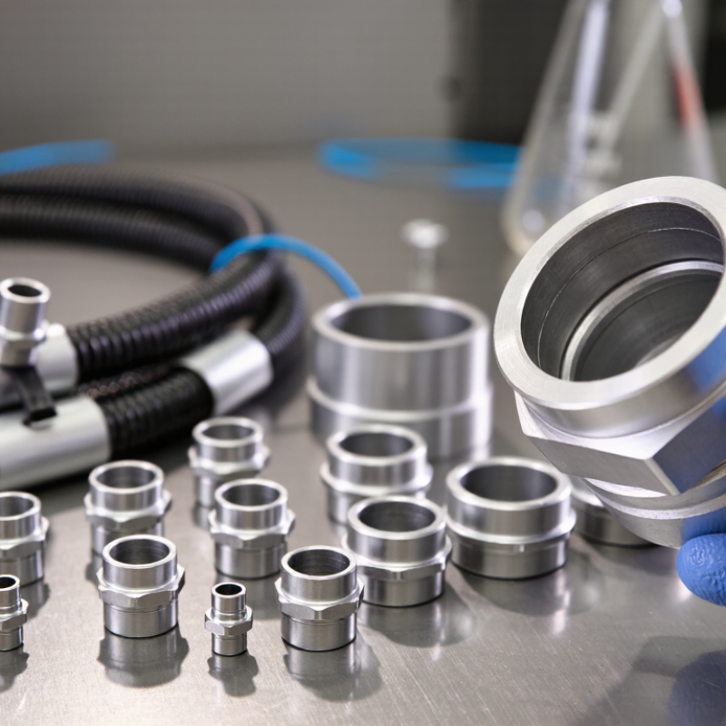
Table of Contents [Hide]
Aluminum Ferrule Definition, Geometry, and Core Industrial Functions
An aluminum ferrule is a small metal sleeve used to secure, join, or terminate a flexible component. It may hold a wire rope, electrical conductor, tube, or braided cable. Common forms include round, oval, and twin-barrel bodies. Geometry matters. The internal bore must match the conductor closely, while wall thickness supports controlled crimping without cracking. Rounded edges reduce abrasion at the cable exit. Short sleeves save space, but longer sleeves can distribute load more evenly.
Manufacturers select aluminum for its low density, conductivity, and natural oxide layer. The International Aluminium Institute reports that recycled aluminum requires about 95% less energy than primary production. That advantage can matter in high-volume assemblies. The USGS Mineral Commodity Summaries 2025 estimated global primary aluminum production at roughly 72 million metric tons in 2024. This large supply base supports broad industrial use, although alloy and temper still require careful verification.
In practice, ferrules provide mechanical retention and strain relief. A crimping tool compresses the sleeve around the cable, creating a stable connection. In electrical work, closed-end ferrules can improve strand containment inside terminal blocks. In lifting assemblies, oval sleeves help form wire-rope eyes when correctly sized and pressed. Not every crimp is reliable. Poor die selection, uneven compression, corrosion, or hidden strand damage can reduce holding strength. Field inspection should check sleeve deformation, cable seating, and load requirements against applicable technical standards. A useful design review may also question whether aluminum is suitable near dissimilar metals, moisture, or repeated vibration.
What Is an Aluminum Ferrule and How Is It Used? - Aluminum Ferrule Definition, Geometry, and Core Industrial Functions
| Data Dimension | Typical Data or Specification | Industrial Meaning and Application |
|---|---|---|
| Definition | A short aluminum sleeve, tube, or compression ring | An aluminum ferrule is fitted over a cable, tube, hose, wire bundle, or other component to provide mechanical support, termination, reinforcement, sealing assistance, or dimensional control. |
| Primary Material | Wrought or cast aluminum alloy | Aluminum alloys are selected for low mass, corrosion resistance, electrical conductivity, and ease of forming. The exact alloy depends on strength, conductivity, joining, and environmental requirements. |
| Density | Approximately 2.65–2.85 g/cm³ for common aluminum alloys | Aluminum ferrules are substantially lighter than comparable steel components, which is useful in aerospace, transportation, electrical, and portable equipment applications. |
| Basic Geometry | Hollow cylindrical sleeve with an internal bore and external diameter | The most common geometry has a round cross-section. Other designs may include flanges, shoulders, grooves, tapered bores, split walls, or preformed ends. |
| Representative Outer Diameter | About 2–25 mm for many small cable and tube ferrules | Larger industrial sleeves can exceed this range. The required outside diameter is determined by the conductor, tube, hose, tooling, clearance, and final assembly envelope. |
| Representative Length | About 3–40 mm for common small ferrules | Longer ferrules may be used where greater load transfer, extended reinforcement, or multiple crimp locations are required. |
| Wall Thickness | Commonly about 0.2–2.0 mm in small formed sleeves | Wall thickness is selected to resist crushing, splitting, vibration, and pull-out while still allowing the ferrule to be crimped, swaged, or formed correctly. |
| Internal Bore | Specified to match the component being inserted, usually with controlled clearance | The bore must accommodate the cable, tube, wire bundle, or hose without excessive looseness. Too little clearance can damage the assembly; too much can reduce grip and alignment. |
| Common Cross-Section Forms | Round, oval, hexagonal, flanged, grooved, and split | Round ferrules are common for cable and tube termination. Hexagonal or indexed profiles can improve crimp repeatability, while flanges and grooves can provide positioning or sealing functions. |
| Conductor Compatibility | Commonly used with aluminum conductors and selected compatible dissimilar-metal connections | Electrical joints must be designed to control oxidation, contact resistance, thermal expansion, and galvanic corrosion. Compatibility depends on the conductor material, terminal design, compound, and installation method. |
| Electrical Conductivity | Approximately 35–65% IACS for many wrought aluminum alloys | Aluminum ferrules can carry electrical current when properly designed and installed. Actual performance depends on alloy, cross-sectional area, contact pressure, surface condition, and joint resistance. |
| Thermal Conductivity | Approximately 120–235 W/m·K for common aluminum alloys | Good heat transfer can help dissipate heat from electrical terminations and mechanically retained components, although the complete assembly determines thermal performance. |
| Melting Point | Approximately 630–660 °C, depending on alloy composition | The ferrule should not be exposed to temperatures near its melting range. Service temperature limits are normally governed by the alloy, temper, insulation, seal, and surrounding components. |
| Cable Termination Function | End sealing, strand retention, strain distribution, and conductor protection | A ferrule can prevent wire strands from spreading, reduce fraying, support a cable end, and create a more consistent interface for terminals or clamps. |
| Tube and Hose Function | Reinforcement, alignment, sleeve joining, and end protection | Tube ferrules can reinforce a tube end, distribute compression loads, help prevent deformation, and support connection systems used in fluid, pneumatic, and instrumentation assemblies. |
| Joining Methods | Crimping, swaging, compression, pressing, riveting, brazing, or welding | The selected method depends on ferrule geometry, wall thickness, alloy, load requirements, production volume, and whether the joint must be removable or permanent. |
| Crimped Joint Principle | Controlled plastic deformation around the inserted component | Crimping creates radial pressure and frictional retention. Correct tooling, die geometry, insertion depth, and crimp force are essential for reliable results. |
| Surface Treatments | Natural oxide film, anodizing, plating, conversion coating, or protective lubricant | Surface treatment may improve corrosion resistance, appearance, wear behavior, or electrical contact performance. The treatment must be compatible with the mating materials and service environment. |
| Corrosion Consideration | Good atmospheric corrosion resistance, with galvanic risk in contact with some metals | Moisture, salts, and direct contact with dissimilar metals can accelerate galvanic corrosion. Isolation, suitable coatings, joint compounds, and compatible hardware may be required. |
| Key Advantages | Low weight, good conductivity, formability, and useful corrosion resistance | These properties make aluminum ferrules suitable for weight-sensitive electrical, mechanical, transportation, telecommunications, fluid-handling, and general industrial assemblies. |
| Main Limitations | Lower hardness than steel, oxide formation, thermal expansion, and possible galvanic interaction | Designers should evaluate crushing, fretting, vibration, temperature cycling, surface oxidation, and compatibility with adjacent materials before selecting an aluminum ferrule. |
| Inspection Checks | Bore size, outside diameter, length, wall thickness, surface condition, and crimp profile | Finished assemblies may also be checked for insertion depth, pull-out force, electrical resistance, leakage, deformation, cracks, and evidence of incomplete or excessive crimping. |

© Copyright - Pro Tool & Supply - Site by SVM E-Marketing Solutions - Sitemap
- Privacy policy