- Products
- Air Compressors & Air Tools
- Climate Control
- Compaction Equipment
- Concrete Cutting Tools & Equipment
- Concrete and Masonry
- Demolition & Excavation
- Electrical & Mechanical
- Fasteners and Anchoring Adhesives
- Floor Protection
- Generators and Welders
- Hand Tools
- Heaters
- Janitorial and Office Supplies
- Jobsite Protection
- Ladders & Storage
- Lighting & Lighting Accessories
- Man Lifts
- Material Handling Equipment
- Power Tools
- Pressure Washers & Pumps
- Safety Gear
- Safety Products
- Saws
- Surface Preparation
- SEASONAL PRODUCTS
- Rentals
- Air Compressor and Air Tool Rentals
- Climate Control Rental
- Compaction Rentals
- Concrete Equipment Rentals
- Demolition & Excavation Equipment Rentals
- Concrete Floor Grinder Rentals
- General Construction Equipment Rentals
- Generator Rentals and Welder Rentals
- Heater Rentals
- Light Tower Rentals
- Man Lift Rentals in Massachusetts and Rhode Island
- Material Handling Equipment Rentals
- Pressure Washer & Pump Rentals
- Saw Rentals in New England
- SEASONAL PRODUCTS
- Products
- Air Compressors & Air Tools
- Climate Control
- Compaction Equipment
- Concrete Cutting Tools & Equipment
- Demolition & Excavation
- Electrical & Mechanical
- Floor Protection
- Generators and Welders
- Construction Heaters
- Construction Ladders, Staging, & Storage
- Construction Lighting
- Man Lifts
- Material Handling Equipment
- Industrial Janitorial and Office Supplies
- Pressure Washers & Pumps
- Construction Safety Products
- Construction Safety Gear
- Surface Preparation
- Building Protection
- Diesel Accessories
- Zero Emissions
- Rentals
- Air Compressor and Air Tool Rentals
- Climate Control Rental
- Compaction Rentals
- Concrete Equipment Rental
- Demolition & Excavation Equipment Rental
- General Construction Equipment Rental
- Generator Rentals and Welder Rentals
- Construction Heaters Rental
- Light Tower Rentals
- Man Lift Rentals
- Material Handling Equipment Rental
- Pressure Washer & Pump Rentals
- Saw Rentals in New England
- Concrete Floor Grinder Rentals
- Zero Emissions Rentals
- Repairs & Used
- Parts
- Blog
- Services
- Resources
- About Us
- Contact Us
Sales & Rental of Construction | Industrial Equipment & Supplies

7 Tips for Choosing Line Filters for Global Buyers?
Choosing line filters for global equipment markets is not a simple catalog exercise. A filter that performs well in a clean laboratory may fail beside a variable-frequency drive, motor, or switching power supply. Installation space, rated current, leakage current, impedance, temperature, and regional approvals all matter.
Industry data supports this concern. Grand View Research’s 2024 EMI shielding market report projects continued growth as manufacturers manage denser electronics and stricter electromagnetic compatibility requirements. MarketsandMarkets’ 2024 EMI Shielding Market report also identifies industrial automation, telecommunications, and automotive systems as important demand areas. These reports do not replace testing. They show why filter selection deserves engineering attention.
Henry W. Ott, a widely respected EMC engineer, wrote, “EMI is a system problem, not a component problem.” That principle guides this article’s seven practical tips for global buyers. Start with the real noise source, not only the visible symptom. Check the filter’s insertion-loss curve at the disturbance frequency. Confirm current ratings under actual temperature conditions. A 10-amp label may not mean 10 amps inside a hot enclosure.
Small details matter.
Verify grounding methods, terminal construction, enclosure space, and certification documents before ordering. IEC 60939 requirements can support consistency, but local installation rules and end-product standards still require review. Buyers should request test conditions, not just impressive performance figures.
There is no universal best filter. Sometimes, a cheaper part passes testing. Sometimes, it creates leakage or resonance problems. That uncertainty deserves honest evaluation, careful sampling, and documented validation before global production.
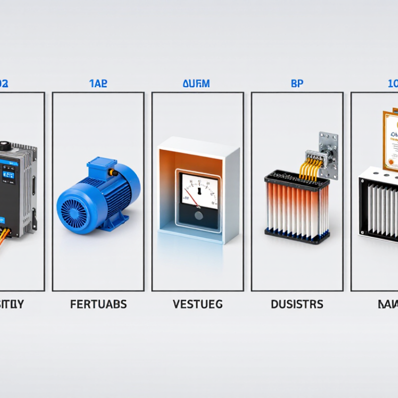
Table of Contents [Hide]
Understanding Line Filter Types and Their Applications
7 Tips for Choosing Line Filters for Global Buyers
Understanding line filter types starts with the noise path. Common-mode filters reduce interference moving along multiple conductors in the same direction. Differential-mode filters control noise traveling between live and neutral lines. Some designs combine both functions. AC filters suit power-entry points, motor cabinets, and switching supplies. DC filters often protect control circuits, sensors, and battery-powered equipment. Signal-line filters require extra care because excessive capacitance can weaken communication quality.
Application details should guide the selection. Check rated voltage, continuous current, temperature range, leakage current, and connector size. A filter rated for 10 amps may overheat when installed in a poorly ventilated enclosure. Fit matters. Also review insertion-loss data at the actual operating frequency, not only the most attractive test point. Noise travels. Cable length, grounding, enclosure material, and load behavior can change results significantly.
Global buyers should request test reports, installation instructions, and applicable safety documentation from qualified suppliers. Regional electrical requirements may differ, so confirm compatibility before ordering large quantities. In practical evaluations, a compact filter can perform poorly when its case lacks a reliable ground connection. Measure twice. A filter that looks perfect on paper may still need adjustment after testing. Engineers sometimes focus too heavily on attenuation and overlook leakage current, maintenance access, or replacement space. That is an easy mistake to make.
© Copyright - Pro Tool & Supply - Site by SVM E-Marketing Solutions - Sitemap
- Privacy policy