Sales & Rental of Construction | Industrial Equipment & Supplies

2026 Top Vacuum Furnace Heat Treatment Equipment Guide

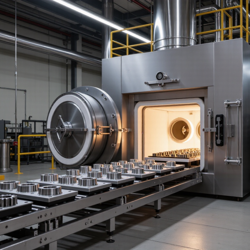
The 2026 Top Vacuum Furnace Heat Treatment Equipment Guide examines how modern furnaces support cleaner, tighter, and more repeatable production. Vacuum Furnace Heat Treatment removes oxygen from the chamber, reducing oxidation, scaling, and surface contamination. That matters when processing tool steel, titanium components, aerospace parts, and precision molds.

As metallurgy expert Dr. George E. Totten explains, “Heat treatment is the controlled heating and cooling of metals to change their properties.” This principle remains practical inside a vacuum furnace. Operators monitor temperature uniformity, pressure stability, gas quenching, loading patterns, and cooling rates. A bright component surface can still hide uneven hardness. That is where testing becomes essential.

This guide compares furnace types, heating systems, pumping performance, quenching methods, control technologies, and maintenance requirements. It also considers energy use and chamber size. Bigger is not automatically better. An oversized furnace may waste power and reduce process efficiency. A compact furnace may limit production flexibility.

Real experience often exposes the gap between specifications and results. Door seals age. Thermocouples drift. Fixtures distort airflow. Small details matter.

The discussion also recognizes an uncomfortable truth: no furnace guarantees perfect treatment without disciplined process control. Reliable results require validated recipes, calibrated instruments, documented inspections, and trained operators. Readers will find practical criteria for selecting equipment that fits materials, production volume, quality targets, and future expansion. Some recommendations remain conditional, because each factory has different constraints. That uncertainty deserves honest attention.
2026 Top Vacuum Furnace Heat Treatment Equipment Guide

Vacuum Furnace Fundamentals: 10⁻²–10⁻⁶ mbar and 600–1,350°C

Vacuum furnace heat treatment depends on two working limits: pressure and temperature. Typical systems operate from 10⁻² to 10⁻⁶ mbar and 600–1,350°C. At 10⁻² mbar, the furnace reduces oxidation during routine heating. At 10⁻⁶ mbar, it supports cleaner processing for sensitive alloys and demanding surface requirements. Pressure alone does not guarantee quality.

A reliable cycle begins with clean loading and controlled pump-down. Oils, moisture, cutting fluids, and trapped air can cause pressure spikes. Watch the pressure curve, not only the final reading. A stable reading near 10⁻⁵ mbar may indicate proper outgassing, but it can also hide a small leak. That assumption is wrong. Leak testing and routine sensor checks remain essential.

Temperature uniformity matters just as much. A furnace rated for 1,350°C may not hold that temperature evenly across a heavy load. Use calibrated thermocouples and record the load temperature when possible. Thin parts may heat quickly, while dense fixtures respond slowly. Real cycles are less tidy. Operators should review ramp rates, soak time, cooling speed, and pressure changes after every run. In practice, the best equipment is not the fastest furnace, but the one that produces repeatable results with traceable data.

2026 Top Vacuum Furnace Heat Treatment Equipment Guide

Vacuum Furnace Fundamentals: 10⁻²–10⁻⁶ mbar and 600–1,350°C

The chart shows typical temperature windows for common vacuum heat-treatment processes. Vacuum brazing and annealing generally operate at lower temperatures, while hardening and sintering require higher temperatures. Typical working pressures range from approximately 10⁻² mbar for less demanding applications to 10⁻⁶ mbar for high-cleanliness or high-temperature processes. Actual cycle settings depend on alloy composition, part geometry, loading, and required surface quality.

Equipment Types: Single-Chamber, Multi-Chamber, and 2–20 bar Gas Quench

2026 Top Vacuum Furnace Heat Treatment Equipment Guide

Single-chamber vacuum furnaces remain practical for mixed production and smaller batches.

Their compact layout simplifies loading, maintenance, and recipe control. Vacuum heating limits oxidation, but fixture design still affects distortion and temperature uniformity. A 2024 U.S. Department of Energy Industrial Decarbonization Roadmap identifies process heating as 51% of industrial energy use. Efficient insulation and shorter transfer times therefore matter financially, not only technically. The weak point is throughput. One chamber must heat, quench, and cool sequentially.

Multi-chamber systems separate heating, quenching, and loading operations.

This design can improve productivity when production volumes remain stable. It also reduces atmospheric exposure during transfers. However, additional chambers increase controls, sealing points, maintenance demands, and operator training. The International Energy Agency’s Energy Efficiency 2023 report continues to emphasize process optimization as a major industrial energy-saving opportunity. Engineers should verify actual cycle data before approving capacity claims. A brochure is not a production study.

Gas quench pressure usually ranges from 2 to 20 bar.

Lower pressure can reduce distortion and operating cost. Higher pressure generally improves cooling intensity for demanding steels and complex geometries. Nitrogen is common, while helium offers faster heat extraction but higher operating expense. Cooling performance depends on gas velocity, nozzle layout, load spacing, and component mass. Pressure matters. A 20-bar system does not automatically deliver better parts. In practical trials, uneven loading can create soft spots or unexpected distortion. That uncomfortable result deserves investigation, not excuses. ASME and ASM heat-treatment guidance also support measuring temperature uniformity, quench performance, and repeatability before production release.

Operating Sequence: Pumpdown, Heating at 5–20°C/min, Quenching, and Cooling

2026 Top Vacuum Furnace Heat Treatment Equipment Guide

Operating a vacuum furnace starts with a controlled pumpdown. Inspect door seals, thermocouple connections, and load cleanliness before closing the chamber. Record the pressure curve. A slow pressure drop may indicate moisture, contamination, or a small leak. Small gaps matter. Keep parts spaced for stable gas circulation and avoid contact between dissimilar components.

During heating, use a programmed rate between 5 and 20°C/min. Lower rates reduce thermal stress in complex or thick parts. Faster rates may improve productivity but can increase temperature differences across the load. Monitor multiple zones, not only the furnace setpoint.

The coldest location determines when the load is truly ready for soaking. Allow sufficient time for temperature equalization. This step is often shortened, and that decision can weaken consistency.

Quenching should begin only after the specified soak is complete and the chamber conditions are stable. Introduce clean, dry gas at a controlled pressure and flow rate. Excessive flow can distort thin sections, while insufficient flow may reduce hardness uniformity. Watch pressure, fan operation, and temperature response together. Cooling under vacuum or low pressure may protect sensitive surfaces, but it can extend the cycle. A perfect program on paper can still fail when the load is packed poorly. Review actual temperature records after every difficult batch, especially when distortion or uneven hardness appears.

Material Process Windows: Tool Steels at 1,000–1,250°C and Titanium Below 950°C

2026 Top Vacuum Furnace Heat Treatment Equipment Guide

Material Process Windows: Tool Steels at 1,000–1,250°C and Titanium Below 950°C

In vacuum heat treatment, temperature is only one part of the process window. Tool steels may require 1,000–1,250°C, but the correct setpoint depends on grade, section thickness, and prior condition. A small overshoot can enlarge austenite grains or increase distortion. I would verify the recipe against the material certificate and an approved datasheet. Use calibrated load thermocouples, not the furnace display alone. Watch the load.

During heating, staged ramps reduce thermal shock in complex dies. Equalize near 600–800°C when the procedure supports it. Then austenitize within the selected band; soak time should follow section size, not clock habit. Vacuum should limit oxidation, while partial-pressure gas can reduce evaporation from sensitive surfaces. High-pressure gas quenching must match steel hardenability and geometry. Thin punches cool quickly; thick blocks may not. Hardness mapping often reveals uneven cooling better than one surface reading.

Titanium needs stricter surface protection. Keep treatment below 950°C unless the metallurgy specifically permits higher temperatures. Oxygen, nitrogen, and moisture can create a brittle alpha case. Clean fingerprints and residues before loading. Clean surfaces matter. Use high vacuum or controlled inert gas, with leak checks before heating. A slow ramp can help thick parts, but excessive holding wastes time and may grow grains. Not every load behaves. In practice, I have sometimes trusted a familiar cycle too much; titanium exposed that weakness through discoloration and altered hardness. Confirm the result with hardness testing, metallography, and dimensional inspection.

2026 Top Vacuum Furnace Heat Treatment Equipment Guide - Material Process Windows: Tool Steels at 1,000–1,250°C and Titanium Below 950°C

Typical starting windows for vacuum-furnace cycle development. Actual temperatures, holding times, pressure levels, and cooling rates must be confirmed against the material producer’s datasheet, part geometry, loading density, and required mechanical properties.

Temperature values are shown in degrees Celsius. Vacuum levels are indicative operating ranges and should be adapted to furnace design, workload, surface requirements, and the risk of vaporization or contamination.
Material / Grade Material Family Typical Process Austenitizing / Solution Temperature Typical Soak Time Indicative Vacuum Range Recommended Cooling Approach Primary Process Considerations
AISI H13 / 1.2344 Hot-work tool steel Vacuum hardening and tempering 1,010–1,030°C Approximately 20–30 minutes after equalization 10−2–10−4 mbar High-pressure gas quench; commonly nitrogen Use staged preheating to reduce thermal gradients. Double tempering is commonly applied, often around 540–650°C depending on hardness and toughness targets.
AISI D2 / 1.2379 Cold-work tool steel Vacuum hardening and double tempering 1,020–1,050°C Approximately 20–30 minutes after equalization 10−2–10−4 mbar High-pressure gas quench; oil quench may be specified for heavy sections High carbon and chromium content can promote retained austenite. Cryogenic treatment may be used in selected specifications, followed by tempering.
AISI M2 / 1.3343 High-speed steel Vacuum hardening with multiple tempering 1,180–1,230°C Approximately 60–90 seconds per 25 mm after equalization 10−3–10−5 mbar Rapid high-pressure gas quench; interrupted cooling can be used for distortion control The high austenitizing temperature requires accurate control and effective load shielding. Triple tempering is commonly used for dimensional stability.
AISI M42 / 1.3247 Cobalt high-speed steel Vacuum hardening and multiple tempering 1,160–1,210°C Approximately 60–90 seconds per 25 mm after equalization 10−3–10−5 mbar High-pressure gas quench with controlled cooling through the transformation range Maintain a clean vacuum and avoid excessive surface reaction. Tempering is normally performed more than once to reduce retained austenite and stabilize hardness.
AISI S7 / 1.2709-type shock-resistant grades Shock-resistant tool steel Vacuum hardening and tempering 1,000–1,030°C Approximately 20–30 minutes after equalization 10−2–10−4 mbar Gas quench sized for section thickness and distortion limits A lower end of the austenitizing range generally supports toughness, while the higher end may increase hardness. Temper promptly after quenching.
AISI T1 / 1.3355 Tungsten high-speed steel Vacuum hardening and multiple tempering 1,190–1,230°C Approximately 60–90 seconds per 25 mm after equalization 10−3–10−5 mbar Rapid high-pressure gas quench Use precise temperature measurement near the load. Excessive soak can increase grain growth and undesirable carbide dissolution.
Commercially Pure Titanium, Grades 1–2 Titanium Vacuum stress relief or annealing 550–760°C Approximately 30–120 minutes, depending on section size 10−3–10−5 mbar Furnace cooling or controlled gas cooling Titanium readily reacts with oxygen, nitrogen, and hydrogen at elevated temperature. Use clean, dry vacuum conditions and limit exposure at high temperature.
Ti-6Al-4V, Grade 5 Alpha-beta titanium alloy Stress relief or sub-transus annealing 700–800°C Approximately 60–120 minutes 10−3–10−5 mbar Air cooling, controlled gas cooling, or furnace cooling according to specification For conventional annealing, avoid exceeding the beta-transus region unless a specialized solution treatment is intended. Surface color and oxygen pickup should be monitored.
Ti-6Al-4V ELI, Grade 23 Medical-grade titanium Stress relief or annealing 650–800°C Approximately 60–120 minutes 10−4–10−5 mbar Controlled gas cooling or furnace cooling Use stricter contamination control than for general-purpose work. Surface chemistry and alpha-case formation can be critical for fatigue-sensitive components.
Ti-6246 High-strength alpha-beta titanium alloy Stress relief or duplex annealing 700–900°C Approximately 60–120 minutes 10−4–10−5 mbar Controlled gas cooling; follow the alloy-specific specification The selected cycle influences strength, ductility, and transformed beta morphology. Avoid uncontrolled oxygen or nitrogen ingress during heating and cooling.
Ti-5Al-2.5Sn Near-alpha titanium alloy Stress relief or annealing 700–850°C Approximately 60–120 minutes 10−4–10−5 mbar Furnace cooling or controlled gas cooling Temperature uniformity is important for dimensional stability. Confirm allowable surface oxygen content when the component is used in fatigue-critical service.
Ti-3Al-2.5V Alpha-beta titanium alloy Stress relief or annealing 650–800°C Approximately 30–90 minutes 10−3–10−5 mbar Air cooling or controlled gas cooling Commonly processed below the beta-transus temperature. Minimize handling contamination and use clean fixtures compatible with titanium.
Equipment selection notes: A vacuum furnace for tool steels should provide accurate temperature control, staged preheating, programmable high-pressure gas quenching, and repeatable pressure regulation. Titanium processing benefits from low-leak-rate construction, clean hot-zone materials, reliable vacuum measurement, low residual-gas contamination, and controlled cooling. Soak times listed above are starting points and should be calculated from the actual load temperature and the thickest section of the workpiece.

Quality Metrics: AMS2750 Class 2 Uniformity of ±5.6°C and Oxygen Control

2026 Top Vacuum Furnace Heat Treatment Equipment Guide

AMS2750 Class 2 uniformity is often presented as ±5.6°C, but buyers should verify the applicable revision and temperature range. A ±5.6°C band equals approximately ±10°F. It should not be labeled Class 2 without checking the exact AMS2750 table. SAE AMS2750H defines survey methods, thermocouple requirements, and furnace classification. A certified temperature uniformity survey should cover empty and loaded conditions, not only a convenient test run. Small chamber corners can behave differently.

Oxygen control needs equal attention. Record chamber pressure, oxygen concentration, leak rate, and recovery time after evacuation. A zirconia sensor may show low oxygen while moisture remains trapped in insulation. That is a practical warning. NIST Technical Note 1297 explains that measurement uncertainty should include calibration, repeatability, and sensor drift. Report uncertainty with a defined coverage factor, commonly k=2, near 95% confidence. Do not trust one perfect cycle. Review trend charts across several batches. A useful acceptance record includes oxygen readings before heating, during the hold, and after backfill. ASTM E220 calibration practices can support thermocouple traceability, while ISO/IEC 17025 laboratory records strengthen audit evidence. I would also challenge the ±5.6°C figure when the workload changes; fixtures, load density, and alloy surface area can shift both temperature and oxygen behavior. The number is useful, but the test conditions matter more.

© Copyright - Pro Tool & Supply - Site by SVM E-Marketing Solutions - Sitemap - Privacy policy
