- Products
- Air Compressors & Air Tools
- Climate Control
- Compaction Equipment
- Concrete Cutting Tools & Equipment
- Concrete and Masonry
- Demolition & Excavation
- Electrical & Mechanical
- Fasteners and Anchoring Adhesives
- Floor Protection
- Generators and Welders
- Hand Tools
- Heaters
- Janitorial and Office Supplies
- Jobsite Protection
- Ladders & Storage
- Lighting & Lighting Accessories
- Man Lifts
- Material Handling Equipment
- Power Tools
- Pressure Washers & Pumps
- Safety Gear
- Safety Products
- Saws
- Surface Preparation
- SEASONAL PRODUCTS
- Rentals
- Air Compressor and Air Tool Rentals
- Climate Control Rental
- Compaction Rentals
- Concrete Equipment Rentals
- Demolition & Excavation Equipment Rentals
- Concrete Floor Grinder Rentals
- General Construction Equipment Rentals
- Generator Rentals and Welder Rentals
- Heater Rentals
- Light Tower Rentals
- Man Lift Rentals in Massachusetts and Rhode Island
- Material Handling Equipment Rentals
- Pressure Washer & Pump Rentals
- Saw Rentals in New England
- SEASONAL PRODUCTS
- Products
- Air Compressors & Air Tools
- Climate Control
- Compaction Equipment
- Concrete Cutting Tools & Equipment
- Demolition & Excavation
- Electrical & Mechanical
- Floor Protection
- Generators and Welders
- Construction Heaters
- Construction Ladders, Staging, & Storage
- Construction Lighting
- Man Lifts
- Material Handling Equipment
- Industrial Janitorial and Office Supplies
- Pressure Washers & Pumps
- Construction Safety Products
- Construction Safety Gear
- Surface Preparation
- Building Protection
- Diesel Accessories
- Zero Emissions
- Rentals
- Air Compressor and Air Tool Rentals
- Climate Control Rental
- Compaction Rentals
- Concrete Equipment Rental
- Demolition & Excavation Equipment Rental
- General Construction Equipment Rental
- Generator Rentals and Welder Rentals
- Construction Heaters Rental
- Light Tower Rentals
- Man Lift Rentals
- Material Handling Equipment Rental
- Pressure Washer & Pump Rentals
- Saw Rentals in New England
- Concrete Floor Grinder Rentals
- Zero Emissions Rentals
- Repairs & Used
- Parts
- Blog
- Services
- Resources
- About Us
- Contact Us
Sales & Rental of Construction | Industrial Equipment & Supplies


2026 Best Vacuum Brazing Process Guide for Buyers?
In 2026, buyers need more than a low quote when comparing vacuum brazing suppliers. The Vacuum Brazing Process can join complex metal parts with clean, precise joints, but results depend on materials, part design, and controlled production conditions. A joint that looks sound may still fail inspection if the assembly, filler metal, or temperature profile is poorly matched.
That sounds simple. It isn’t.
This guide explains the choices buyers should examine before requesting a quotation. These include base metals, joint clearance, furnace capacity, temperature uniformity, atmosphere control, and inspection methods. Ask how the supplier handles sample runs, process records, and dimensional checks. For example, a small gap between components can affect filler flow, while an uneven heating cycle may distort a thin assembly. Those details deserve attention before production begins.
No single supplier or process setting suits every component. Some trade-offs are easy to miss. A lower price may reflect different inspection coverage or a narrower service scope, so compare like with like. This guide offers practical questions for reviewing capabilities and estimating project fit, not a substitute for engineering validation. Share drawings, material specifications, and performance requirements with qualified specialists, then confirm the proposed process through suitable testing. A careful review can reduce surprises. It cannot remove every risk.
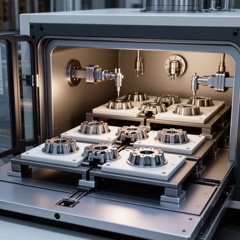
Table of Contents [Hide]
What Vacuum Brazing Is and How the Process Works
Vacuum brazing joins metal components by melting a filler metal while keeping the base materials solid. The parts are cleaned, fitted together, and placed in a sealed furnace. Air is removed to reduce oxidation during heating. Surface preparation still matters; vacuum cannot compensate for oil or heavy contamination.
As the furnace reaches the filler metal’s working temperature, the filler melts and flows into the narrow joint by capillary action. The base metals do not melt. That matters. After a controlled hold, the furnace cools the assembly, often under vacuum. The result can be a neat joint with little distortion, especially for complex assemblies that are difficult to weld.
Reliable results depend on more than furnace temperature. Joint clearance, filler selection, material compatibility, and part cleanliness all affect flow and strength. A gap that is too wide may leave an incomplete joint; one that is too tight can restrict filler movement. Not every alloy fits. Parts also need support so they do not shift during heating. Process trials and inspection help confirm the recipe before production. A trial may reveal an awkward detail: a joint that looks simple on a drawing can behave differently once heated.

© Copyright - Pro Tool & Supply - Site by SVM E-Marketing Solutions - Sitemap
- Privacy policy