- Products
- Air Compressors & Air Tools
- Climate Control
- Compaction Equipment
- Concrete Cutting Tools & Equipment
- Concrete and Masonry
- Demolition & Excavation
- Electrical & Mechanical
- Fasteners and Anchoring Adhesives
- Floor Protection
- Generators and Welders
- Hand Tools
- Heaters
- Janitorial and Office Supplies
- Jobsite Protection
- Ladders & Storage
- Lighting & Lighting Accessories
- Man Lifts
- Material Handling Equipment
- Power Tools
- Pressure Washers & Pumps
- Safety Gear
- Safety Products
- Saws
- Surface Preparation
- SEASONAL PRODUCTS
- Rentals
- Air Compressor and Air Tool Rentals
- Climate Control Rental
- Compaction Rentals
- Concrete Equipment Rentals
- Demolition & Excavation Equipment Rentals
- Concrete Floor Grinder Rentals
- General Construction Equipment Rentals
- Generator Rentals and Welder Rentals
- Heater Rentals
- Light Tower Rentals
- Man Lift Rentals in Massachusetts and Rhode Island
- Material Handling Equipment Rentals
- Pressure Washer & Pump Rentals
- Saw Rentals in New England
- SEASONAL PRODUCTS
- Products
- Air Compressors & Air Tools
- Climate Control
- Compaction Equipment
- Concrete Cutting Tools & Equipment
- Demolition & Excavation
- Electrical & Mechanical
- Floor Protection
- Generators and Welders
- Construction Heaters
- Construction Ladders, Staging, & Storage
- Construction Lighting
- Man Lifts
- Material Handling Equipment
- Industrial Janitorial and Office Supplies
- Pressure Washers & Pumps
- Construction Safety Products
- Construction Safety Gear
- Surface Preparation
- Building Protection
- Diesel Accessories
- Zero Emissions
- Rentals
- Air Compressor and Air Tool Rentals
- Climate Control Rental
- Compaction Rentals
- Concrete Equipment Rental
- Demolition & Excavation Equipment Rental
- General Construction Equipment Rental
- Generator Rentals and Welder Rentals
- Construction Heaters Rental
- Light Tower Rentals
- Man Lift Rentals
- Material Handling Equipment Rental
- Pressure Washer & Pump Rentals
- Saw Rentals in New England
- Concrete Floor Grinder Rentals
- Zero Emissions Rentals
- Repairs & Used
- Parts
- Blog
- Services
- Resources
- About Us
- Contact Us
Sales & Rental of Construction | Industrial Equipment & Supplies


2026 Top Insulated Terminals for Global Buyers?
Global buyers face a crowded market for Insulated Terminals in 2026. A low unit price can look attractive on a spreadsheet. On a factory floor, however, a loose crimp, cracked sleeve, or mismatched wire range can cost far more in rework. Small details matter.
MarketsandMarkets estimated the global electrical connectors market at $84.2 billion in 2023, with a projected rise to $111.3 billion by 2028. That broader category includes many products beyond insulated terminals, so the figures are context, not a terminal-specific forecast. Still, they point to sustained demand for dependable electrical connections. Quality expert W. Edwards Deming’s well-known reminder, “In God we trust; all others must bring data,” is useful here: supplier claims should be checked against test records, material specifications, and traceable certifications.
Good connections are verified.
This guide compares leading Insulated Terminals for international purchasing, focusing on crimp consistency, insulation performance, material options, documentation, and supply reliability. Standards such as UL 486A-486B and IEC 61238-1 offer useful reference points for connector evaluation, but buyers should confirm the applicable requirements for each product and application. A standard number alone does not prove a terminal suits a specific conductor, tool, or operating environment. That distinction is easy to overlook. It is also where a comparison can become more useful than a ranking. We will examine what suppliers publish, what buyers should request, and where available evidence leaves unanswered questions. Market growth is not proof of quality. Real confidence comes from verifiable specifications and samples tested under the conditions they will actually face.
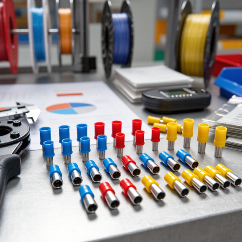
Table of Contents [Hide]
What Insulated Terminals Are and How They Work
Insulated terminals join a wire to a screw, stud, or another conductor. Each has a conductive metal section and a sleeve made from insulating material. The metal carries current; the sleeve helps prevent accidental contact and supports the wire near the connection. Common forms include ring, fork, pin, and butt terminals.
Small details matter. A ring terminal, for example, stays captured under a loosened screw, while a fork terminal can be removed without fully taking off the fastener.
Installation relies on a sound crimp, not the sleeve alone. Strip the wire to the length specified for the terminal, keeping the copper strands intact. Insert them fully, then use a crimping tool matched to the terminal and wire size. A proper crimp should hold firmly, with no loose strands or exposed copper beyond the barrel.
Give it a gentle pull. Color bands often indicate wire-size ranges, but conventions can vary, so check the product specifications rather than relying on color alone.
Not foolproof. Heat, moisture, vibration, and limited space can affect material choice and service life.
Insulation reduces contact risk, but it does not replace suitable protection for the entire electrical assembly. The easy mistake is choosing a terminal that fits the wire but not the actual operating conditions.

© Copyright - Pro Tool & Supply - Site by SVM E-Marketing Solutions - Sitemap
- Privacy policy