- Products
- Air Compressors & Air Tools
- Climate Control
- Compaction Equipment
- Concrete Cutting Tools & Equipment
- Concrete and Masonry
- Demolition & Excavation
- Electrical & Mechanical
- Fasteners and Anchoring Adhesives
- Floor Protection
- Generators and Welders
- Hand Tools
- Heaters
- Janitorial and Office Supplies
- Jobsite Protection
- Ladders & Storage
- Lighting & Lighting Accessories
- Man Lifts
- Material Handling Equipment
- Power Tools
- Pressure Washers & Pumps
- Safety Gear
- Safety Products
- Saws
- Surface Preparation
- SEASONAL PRODUCTS
- Rentals
- Air Compressor and Air Tool Rentals
- Climate Control Rental
- Compaction Rentals
- Concrete Equipment Rentals
- Demolition & Excavation Equipment Rentals
- Concrete Floor Grinder Rentals
- General Construction Equipment Rentals
- Generator Rentals and Welder Rentals
- Heater Rentals
- Light Tower Rentals
- Man Lift Rentals in Massachusetts and Rhode Island
- Material Handling Equipment Rentals
- Pressure Washer & Pump Rentals
- Saw Rentals in New England
- SEASONAL PRODUCTS
- Products
- Air Compressors & Air Tools
- Climate Control
- Compaction Equipment
- Concrete Cutting Tools & Equipment
- Demolition & Excavation
- Electrical & Mechanical
- Floor Protection
- Generators and Welders
- Construction Heaters
- Construction Ladders, Staging, & Storage
- Construction Lighting
- Man Lifts
- Material Handling Equipment
- Industrial Janitorial and Office Supplies
- Pressure Washers & Pumps
- Construction Safety Products
- Construction Safety Gear
- Surface Preparation
- Building Protection
- Diesel Accessories
- Zero Emissions
- Rentals
- Air Compressor and Air Tool Rentals
- Climate Control Rental
- Compaction Rentals
- Concrete Equipment Rental
- Demolition & Excavation Equipment Rental
- General Construction Equipment Rental
- Generator Rentals and Welder Rentals
- Construction Heaters Rental
- Light Tower Rentals
- Man Lift Rentals
- Material Handling Equipment Rental
- Pressure Washer & Pump Rentals
- Saw Rentals in New England
- Concrete Floor Grinder Rentals
- Zero Emissions Rentals
- Repairs & Used
- Parts
- Blog
- Services
- Resources
- About Us
- Contact Us
Sales & Rental of Construction | Industrial Equipment & Supplies


10 Tips for Choosing Pneumatic Valves?
Choosing the right Pneumatic Valves can determine whether a machine runs smoothly or wastes energy every shift. These components control air direction, pressure, speed, and actuator movement. A small mismatch can cause slow cylinders, noisy exhaust, or repeated downtime. The details matter.
Industry research supports careful selection. The U.S. Department of Energy’s compressed-air guidance reports that leaks can waste 20% to 30% of compressor output in poorly maintained systems. That figure makes valve sealing, fitting quality, and maintenance access practical concerns, not minor specifications. ISO 4414 also emphasizes safe design, pressure control, and predictable pneumatic-system behavior. Meanwhile, market analyses from Grand View Research and MarketsandMarkets identify automation, packaging, and manufacturing as major demand areas for pneumatic equipment.
This guide explains ten useful checks for selecting Pneumatic Valves. It considers valve function, port size, operating pressure, flow capacity, response time, media quality, materials, control voltage, installation space, and service life. Real-world experience still matters. A catalog rating may look excellent, yet performance can change with long tubing, moisture, temperature, or poor filtration. That is easy to overlook.
No checklist is perfect.
The best choice balances engineering data with the machine’s actual working conditions. Engineers should verify manufacturer specifications, test samples when possible, and document assumptions before purchase. These steps support reliable decisions and help avoid expensive substitutions after installation. Some applications need a specialist review, especially where personnel safety or critical production equipment is involved.
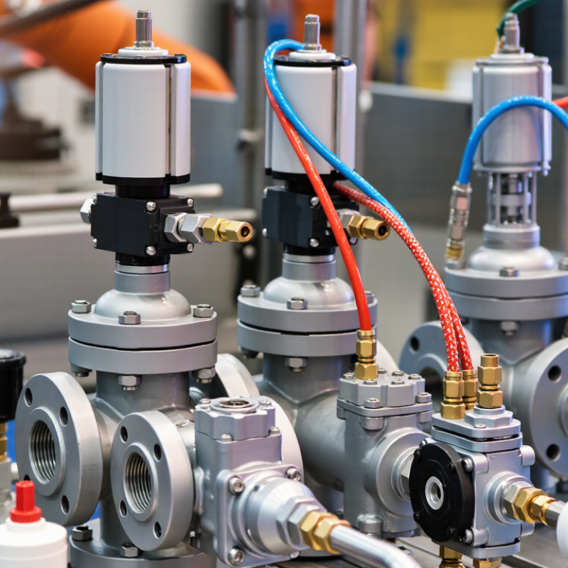
Table of Contents [Hide]
Define the Application and Performance Requirements
Define the application before comparing pneumatic valves. Record the working medium, pressure range, temperature, flow rate, cycle frequency, and available air quality. A valve for clean, dry air may fail quickly in a wet or dusty environment. The piping size also matters. Oversizing can reduce control accuracy, while undersizing creates pressure loss and slow actuator movement.
Tip: Describe the real operating cycle. Will the valve switch twice daily or every few seconds? Specify the actuator volume, required response time, and preferred fail position during air loss. Consider whether the system needs normally open, normally closed, or proportional control. I have seen projects focus on maximum pressure while overlooking minimum pressure. That small omission caused unreliable movement during plant start-up.
Tip: Test the difficult conditions, not only the ideal ones. Check cold starts, pressure fluctuations, contaminated air, and long idle periods. Confirm connection standards, seal compatibility, noise limits, and maintenance access. A manual override may help during inspection, but it can introduce accidental operation if poorly protected. My own early checklists sometimes missed installation orientation. That mistake was minor on paper, yet it complicated drainage and servicing. Ask operators to review the layout before approval. Their practical feedback often exposes problems that specifications do not show.

© Copyright - Pro Tool & Supply - Site by SVM E-Marketing Solutions - Sitemap
- Privacy policy